1.17 V3 MU – FOU FUNCTIONAL BLOCK DIAGRAM
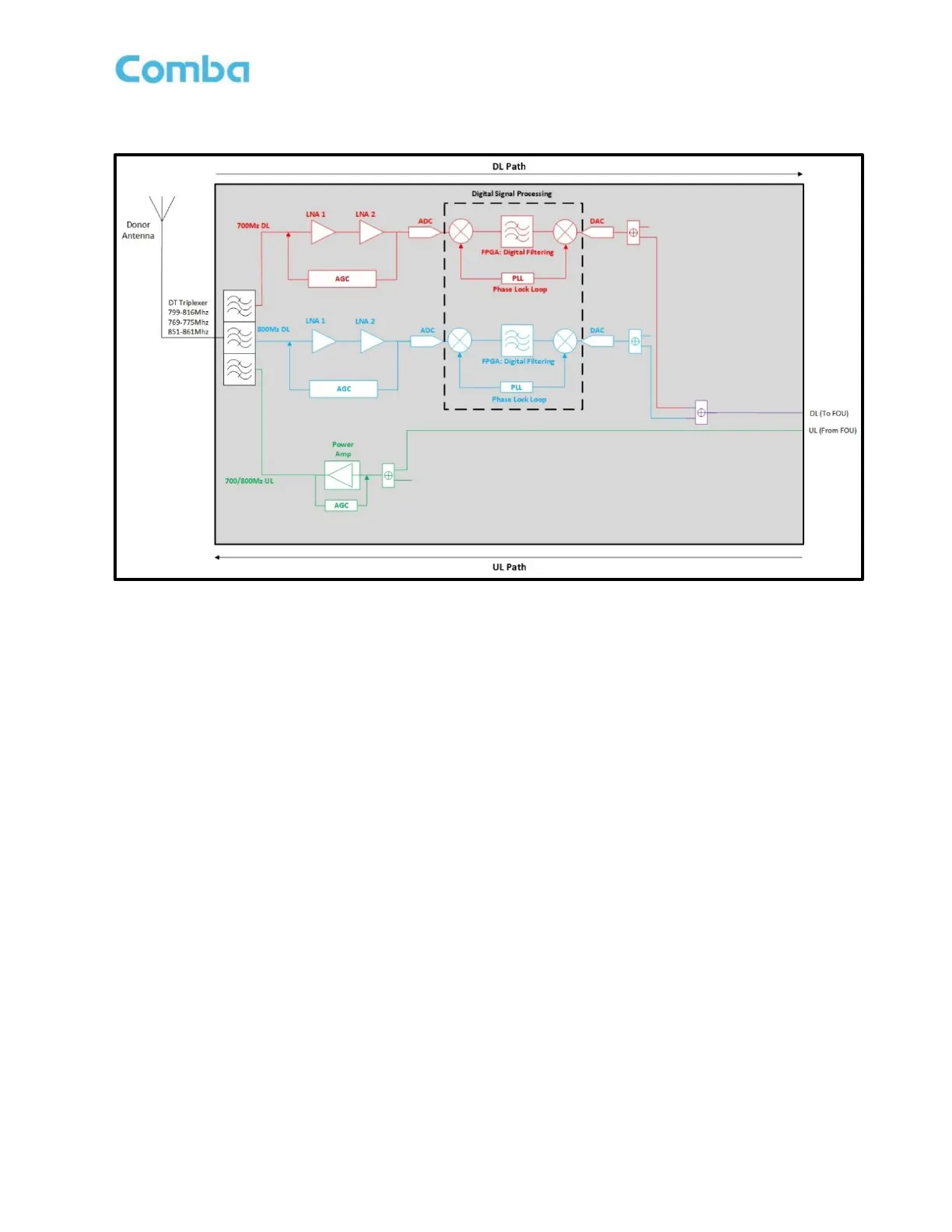
Figure 10: V3 MU to FOU Functional Block Diagram
Note: The above block diagram shows the 700MHz DL path in red, the 800MHz DL path in Blue, the
700/800MHz combined DL path in purple, and the 700/800MHz combined UL path in green.
Note: The BDA and MU are the same device. The only difference is the software configuration. When using
the device in a fiber DAS configuration, the software must be in “DAS” mode for correct operation. DL OUT
and UL IN FOU ports located on the BDA/MU are used to interconnect to the Fiber Optic Expansion Unit (FOU).
For simplicity, BDA components not related to the end-to-end Fiber DAS RF paths have been omitted from
Figure 10.
In the downlink path, the BTS signals are received by the donor antenna of the BDA/MU and fed to the DT port.
The DT Triplexer will allow only DL signals within the DL passband to enter the DL path of the BDA/MU and
will reject all others. The DT Triplexer will also separate the 700MHz and 800MHz DL signals so they can be
conditioned separately. After the DT Triplexer, the signals enter the LNA modules for pre-amplification and
then pass to the digital RF integrated module for digital filtering and frequency conversion. Once the DL signals
have been digitally processed, the 700 and 800MHz DL signals are coupled off before the DL PAs and are
combined to feed the DL OUT FOU port. The DL signals are finally transmitted at the DL OUT FOU port towards
the FOU.
In the uplink path, the UL signals received from the FOU are fed into the BDA/MU through the UL IN FOU port
and coupled into the UL path before the UL PA. Then the UL signals enter the UL PA for a final gain boost to
amplify to final target power. After amplification, the UL signals will enter the DT Triplexer for final
combining/filtering, rejecting all wideband noise from the UL PA, and only passing the desired signals within
the 700MHz and 800MHz UL passbands. The UL signals are finally transmitted at the DT port towards donor
antenna.