CRITICALPOINT 700/800MHZ BDA/DAS/BBU V3 USER MANUAL
©2024 Comba Telecom. All Rights Reserved.
568 Gibraltar Drive, Milpitas, CA 95035 | +1 408 526 0180
Rev. 1-0-2 Rev. Date: 11-1-2024
6.5 ALARM INDICATORS IN THE WEB GUI
There are several pages of the user GUI that contain alarm status indicators and/or alarm configuration
parameters. See Tables 31 and 32 below which describe where the alarm status indicators and
configuration parameters can be found in the V3 BDA/MU/RU devices
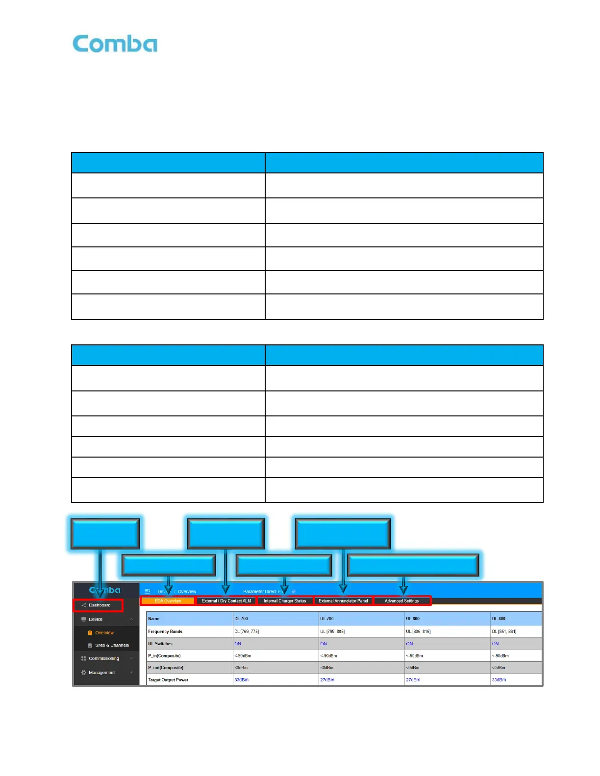
Table 31: V3 BDA - Web GUI Alarm Configuration and Status
View of all dry contact alarm status. View of all current
system alarms.
Device – Overview– BDA Overview
General device alarm status. 700MH/800MHz band specific
alarm status
Device – Overview– External/Dry Contact
ALM
External Alarms and Dry Contact Alarms
Device – Overview– Internal Charger
Status
Power Supply and Battery Charger status and alarms.
Device – Overview – External
Annunciator Panel
Comba External Annunciator Panel status and alarms.
Device – Overview – Advanced Settings
Settings for Oscillation Alarm and Antenna Disconnection
Alarm.
Table 32: V3 Fiber DAS – Web GUI Alarm Configuration and Status
View of all dry contact alarm status. View of all current
system alarms.
Home – Device Checkbox - Overview
General device alarm status. 700MH/800MHz band specific
alarm status
Home – Device Checkbox – Alarm
External Alarms and Dry Contact Alarms
Home – Device Checkbox – BBU
Power Supply and Battery Charger status and alarms.
Home – Device Checkbox – AP
Comba External Annunciator Panel status and alarms.
Home – Device Checkbox – Advanced
Settings for Oscillation Alarm and Antenna Disconnection
Alarm.
Figure 182: V3 BDA/MU/RU – Web GUI Alarm Configuration and Status
Dry Contact &
External Alarms
External Annunciator
Panel Alarms
Osc. and Donor Antenna Alarms