CRITICALPOINT 700/800MHZ BDA/DAS/BBU V3 USER MANUAL
©2024 Comba Telecom. All Rights Reserved.
568 Gibraltar Drive, Milpitas, CA 95035 | +1 408 526 0180
Rev. 1-0-2 Rev. Date: 11-1-2024
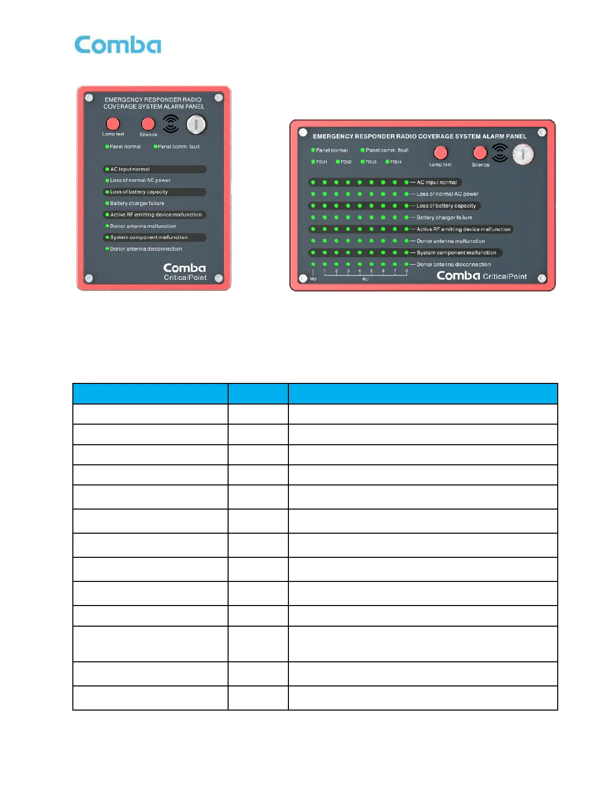
Figure 181: V3 AP Default LED Alarm Configuration UL2524 2018 2
nd
Revision
Table 30: V3 AP Default LED Alarm Configuration UL2524 2018 2
nd
Revision
When AC input is ok, GREEN. RED if in alarm.
When AC input is not present, ON
When battery voltage is lower than the threshold, ON
When AC/DC module detects fault, ON
Active RF emitting device
malfunction
When the Public safety product generates Booster failure
alarm event, ON
Donor antenna disconnection
When the Public safety product generates Donor Antenna
Disconnection alarm, ON
System component malfunction
When the Public safety product generates System
Component alarm, ON
Donor antenna malfunction
When the Public safety product generates Donor Antenna
malfunction alarm, ON
When the communication between Alarm panel and BBU
unit is abnormal, ON
When Alarm panel works normally, ON
Indicates that the alarm display panel displays alarms for
a specific FOU. When FOU detected, ON
*For APV3-DAS only
Press the lamp test button to perform a lamp self-check
when the key switch is on.
Mute button, which can turn off the buzzer sound when
the key switch is on
 Loading...