7.12 APPENDIX L: V3 FIBER INSTALLATION ADVICE
Best Practices for Public Safety and Cellular Analog Fiber DAS Deployment – Fiber Plant Installation
Introduction:
The purpose of this document is to highlight the proper installation and end-to-end testing of the fiber plant
(aka, fiber backhaul) that is used to optically connect the analog fiber master unit to the analog fiber remote
unit(s). Improper fiber installation and testing will result in increased system integrator troubleshooting and
installation costs, and cause communication performance issues between the fiber master and fiber remote
DAS equipment. It is imperative that proper cleaning techniques and end-to-end fiber testing on the installed
fiber plant (which includes patch panel(s), patch cable(s), fusion splice(s), and connectors) are performed.
Fiber Plant:
For an analog fiber DAS solution, the fiber plant must be deployed with Single-Mode fiber and terminated with
SC/APC (Angle Physical Contact or Angle Polished Connector) connectors.
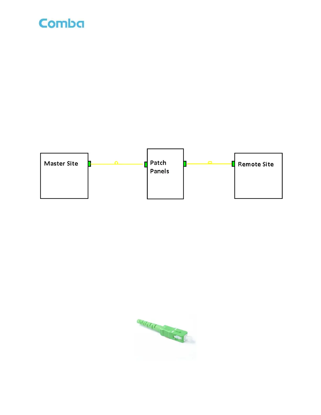
Block Diagram of a Fiber Plant
Once the fiber plant is installed, the system integrator will be required to perform optical test measurements to
ensure that the fiber plant is within operating specifications prior to the installation of any fiber DAS equipment.
The quality of the optical path must be checked throughout the entire length of the fiber plant to determine
optical reliability (aka, end-to-end testing). All fiber connectors, including fusion splicing, must be certified to
meet industry standards. An Optical Time Domain Reflectometer (OTDR) is used to test and certify the optical
performance of the fiber plant by identifying reflection points throughout the entire length of the fiber path. Any
reflections will degrade the linearity of a fiber optic link and introduce noise, thus why it is important to confirm
the fiber is working within tolerance. It is best to keep all discrete reflections to <60 dB.
Differences in SC Fiber Connectors:
The SC/APC connector can be identified by a green connector boot and square body. The fiber end is angle-
polished to 8° and offers a large surface area of contact between the mating connectors. The APC improves
coupling efficiency and minimizes connector back reflection or return loss characteristics, thus keeping the
return loss below <60 dB.
Example of a SC/APC Connector
 Loading...