2.16 V3 SYSTEM ALARM CONNECTION
Dry Contact Alarms:
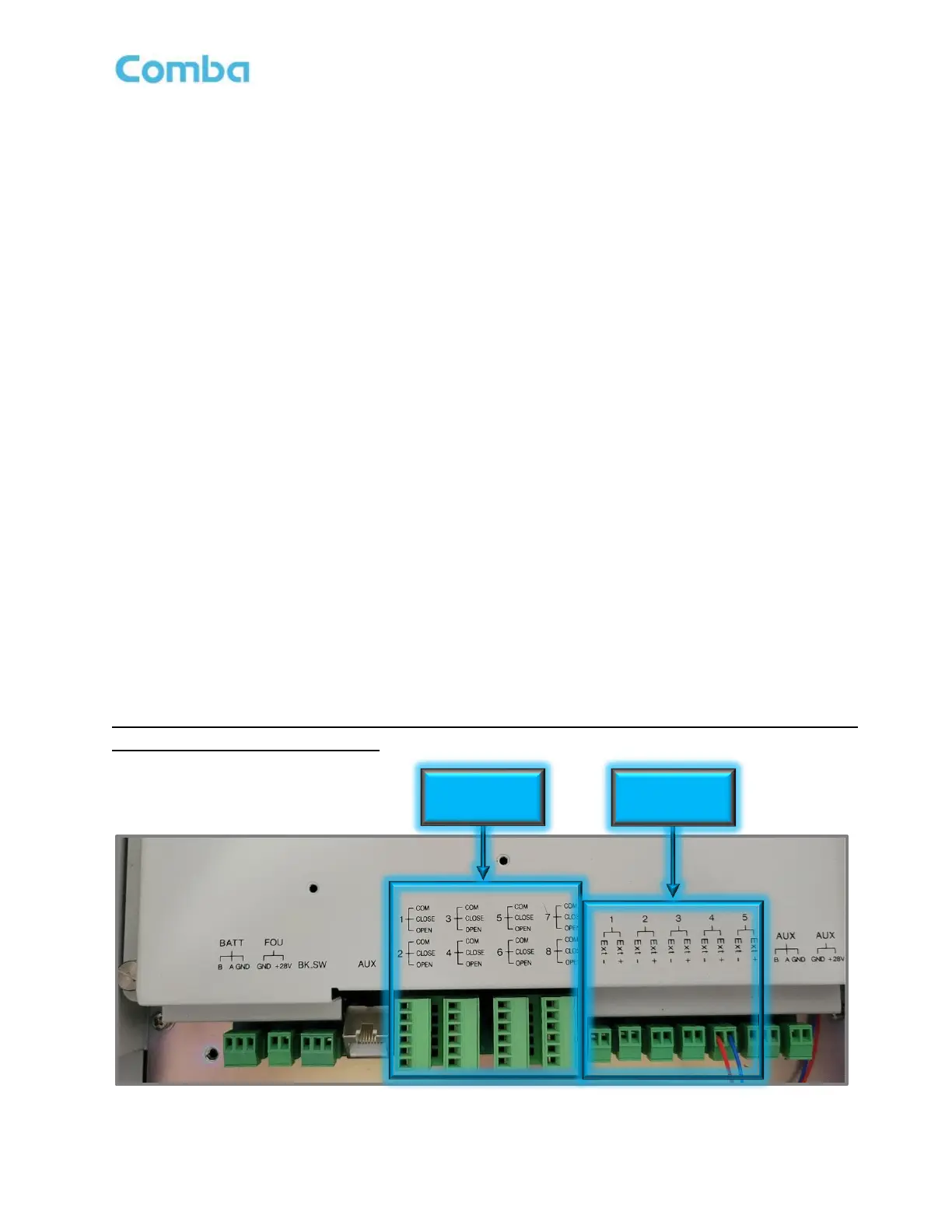
The V3 BDA/MU and RU have 8 dry contact outputs, each one supports either Normally Open or Normally
Closed operation. For Normally Closed operation use the “CLOSE” and “COM” terminals. For Normally
Open operation use the “OPEN” and “COM” terminals. The user can configure each of the 8 dry-contact
alarm outputs through the software GUI. There are default alarm configurations in the software GUI that
match the annunciator front plates that are included with the unit. Furthermore, for non-standard/custom
alarm configurations, the user can select which internal device alarms will trigger each dry-contact alarm
output. In the Fiber DAS configuration, RU alarms are also mirrored and generated at the BDA/MU Dry
Contacts such that the entire system of alarms can be summarized at the BDA/MU. EOL (End-of-Line)
Resistors can be installed across the Dry Contact Alarm terminals. The Phoenix Alarm Connectors are
removable for ease of wire installation.
External Alarms:
The V3 BDA/MU/RU has 5 external alarm inputs which can accept dry contact outputs from external devices.
These external alarms can be setup in the software GUI to trigger from a Normally Open or Normally Closed
device trigger. Furthermore, the external alarm inputs can be configured to trigger one or more of the dry-
contact alarm outputs. Additionally, any of the external alarm inputs can be configured to control the RF and
shut down the RF amplifiers through the software. This allows for a quick RF Shut Down by a simple push of
a button (Example EPO Switch). The External Alarm 5 is pre-configured from the factory as the “Door Open
Alarm”. If the user does not wish to use the Door Open Alarm or requires the External Alarm 5 for a different
device, the Door Alarm wires must be removed. Please ensure the device is completely powered down
before making this wire connection. Install the new device wires in External Alarm 5 and reconfigure
accordingly in the software GUI.
For detailed instructions on how to configure alarms in the software GUI, refer to the Commissioning
and Alarms sections of this manual!
Figure 47: V3 BDA/MU/RU Dry-Contact Output and External Input Alarms Connection
8 x Dry-Contact