©2024 Comba Telecom. All Rights Reserved.
568 Gibraltar Drive, Milpitas, CA 95035 | +1 408 526 0180
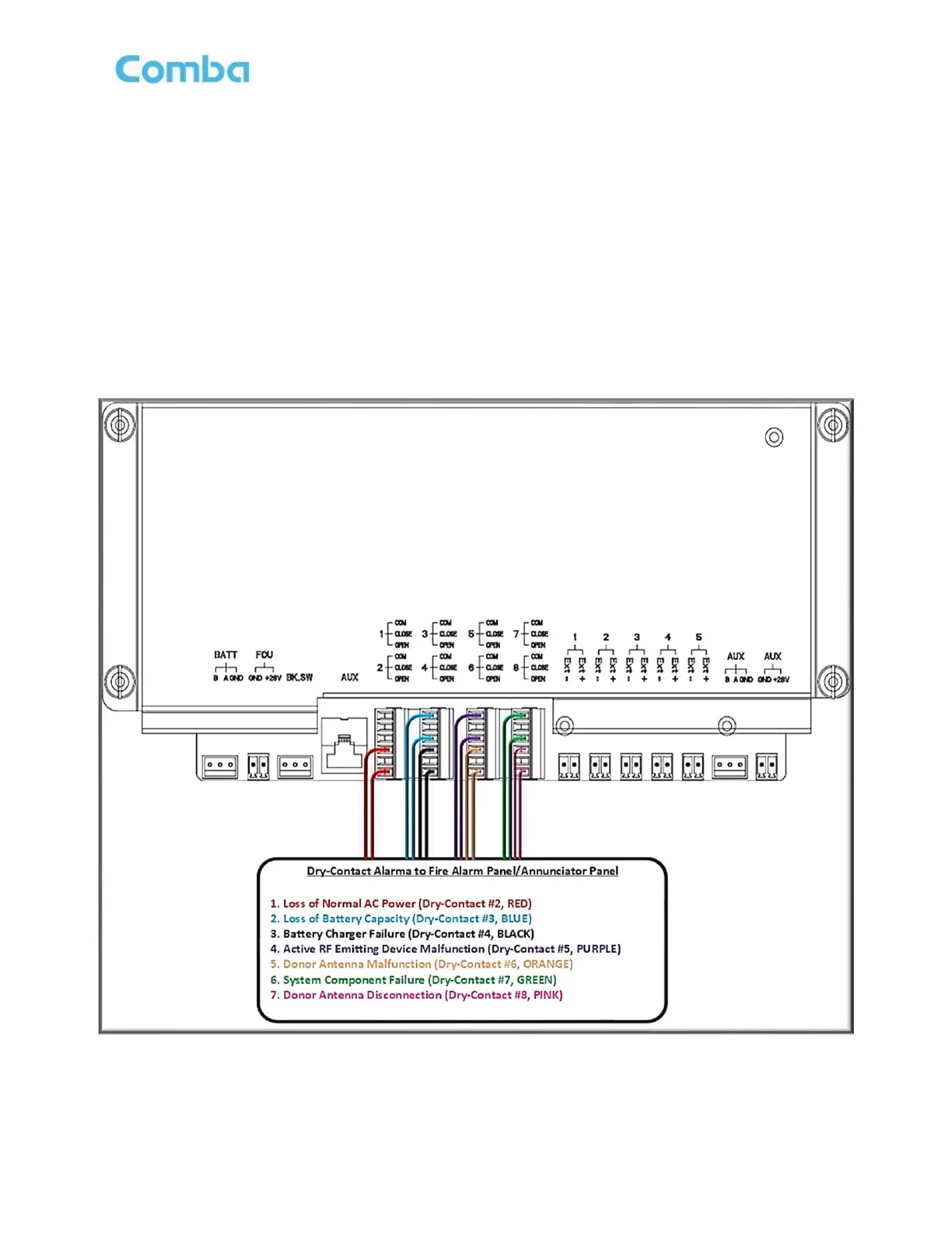
See Figure 48 below for a typical supervisory alarm connection from the BDA/MU/RU to a Fire Alarm Panel.
The example below shows the BDA/MU feeding 7 alarms to the fire alarm panel per the UL2524 2
nd
Rev
2018 standard. This is a common configuration, and Comba provides a setting in the software GUI to easily
configure these alarms. Also, as described in the General Information section, Comba provides several
different front-panel annunciator plates with BDA/MU/RU to match the specific alarm configuration required
by your authority. See Section 2.17 for instructions on how to install/replace the annunciator front plate.
Note: In the Fiber DAS configuration, RU alarms are also mirrored and generated at the BDA/MU Dry
Contacts such that the entire system of alarms can be summarized at the BDA/MU.
Example: If a RU has a “Loss of Normal AC Power” Alarm, the Dry Contact #1 alarm will be triggered at both
the RU and BDA/MU.
Figure 48: V3 BDA/MU/RU NO Dry-Contact Alarm Wiring Example – UL2524 2
nd
Rev Oct 2018