1.19 V3 RU FUNCTIONAL BLOCK DIAGRAM
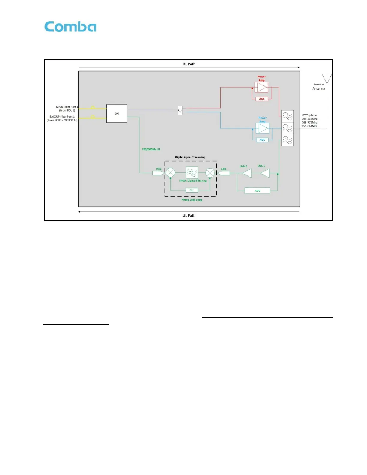
Figure 12: V3 RU Functional Block Diagram
Note: The above block diagram shows the 700MHz DL path in red, the 800MHz DL path in Blue, the
700/800MHz combined DL path in purple, and the 700/800MHz combined UL path in green.
There are two Fiber optic ports installed on the V3 RU. The purpose is to allow for system redundancy for two
MU/FOU’s to feed signals to and from the RU. There is a MAIN Fiber Port 1 and an OPTIONAL BACKUP Fiber
Port 2. When redundancy mode is activated, during normal operation, when all devices are free from alarms,
the RU will Transmit/Receive signals from the MAIN Fiber Port 1. Upon a fiber failure on the MAIN Fiber Port
1, the RU will automatically switch and Transmit/Receive signals on the BACKUP Fiber Port 2. Additionally,
MU Dry Contact alarm can be configured such that user defined MU alarms can feed into an external alarm
input and trigger the RU to switch to the BACKUP Fiber Port 2. In other words, the user has control of which
MU alarms will cause the RU to switch to its BACKUP fiber path. These redundancy features are currently not
available but are planned for release in the future. For now, always connect the fiber to the MAIN Fiber Port 1
for standard applications.
In the downlink path, the DL optical signals are received on the MAIN Fiber Port 1 of the RU. Once the DL
signals enter the RU they are fed to the RF-to-Optical converter. Once the DL signals reach the RF-to-Optical
converters, they are converted from an Optical signal to an RF signal and fed towards the DL PAs from final
amplification. The combined 700/800MHz DL signals are then separated and fed to their respective DL PA.
After final PA amplification, the DL signals will enter the MT Triplexer for final combining/filtering, rejecting all
wideband noise from the DL PAs, and only passing the desired signals within the 700MHz and 800MHz DL
passbands. The DL signals are finally transmitted at the MT port towards service antenna(s).
In the uplink path, the mobile signals from portable radios are received by the service antenna(s) and travel
through a network of passive devices before entering the BDA at the MT port. The MT Triplexer will allow only
UL signals within the UL passband to enter the UL path of the BDA and will reject all others. The MT Triplexer
does not separate the 700MHz and 800MHz signals in the UL path as the bands are directly adjacent to one
another. The 700MHz and 800MHz UL signals use the same amplification path. After the MT Triplexer, the
signals enter the LNA module for pre-amplification and then pass to the digital RF integrated module for digital