CRITICALPOINT 700/800MHZ BDA/DAS/BBU V3 USER MANUAL
©2024 Comba Telecom. All Rights Reserved.
568 Gibraltar Drive, Milpitas, CA 95035 | +1 408 526 0180
Rev. 1-0-2 Rev. Date: 11-1-2024
6.3 V1 AP STATUS LED INDICATORS AND BUZZER
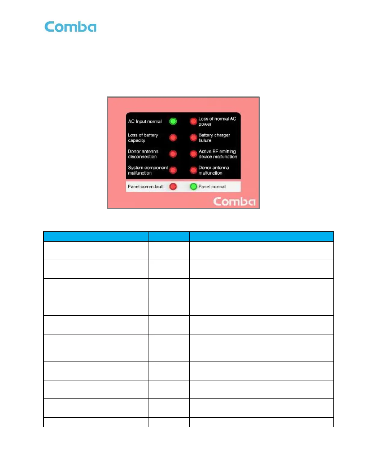
The V1 AP LED indicators help the user to check the equipment status quickly and easily. See below Figure
178 and Table 28 which explain their operation.
Note: The V1 AP LEDs mirror the operation of the V3 BDA/MU/RU front panel annunciator. The V1 AP
can support custom alarm configurations; however, the user must manually modify the front labelling.
Figure 178: V1 AP LED Status Indicators
Table 28: V1 AP LED Status Indicator General Explanation
Normal AC Power Indicator.
Green = Normal/No Alarm; OFF = NO AC Detected
Loss of normal AC power
DRY 1
Loss of normal AC Power Indicator.
ON = alarm; OFF = No alarm.
Loss of battery capacity
DRY 2
Loss of battery capacity Indicator.
ON = alarm; OFF = No alarm.
Battery charger failure
DRY 3
Battery charger failure Indicator.
ON = alarm; OFF = No alarm.
Donor antenna disconnection
DRY 4
Donor antenna disconnection Indicator.
ON = alarm; OFF = No alarm.
Active RF-emitting device
malfunction
DRY 5
Active RF-emitting device malfunction
Indicator.
ON = alarm; OFF = No alarm.
System component malfunction /
DRY 6
System component malfunction Indicator.
ON = alarm; OFF = No alarm.
Donor antenna malfunction
DRY 7
Donor Antenna Malfunction Indicator.
ON = alarm; OFF = No alarm.
Panel Comm. Fault Indicator.
ON = alarm; OFF = No alarm
ON = Panel normal; OFF = Panel fault
 Loading...