CRITICALPOINT 700/800MHZ BDA/DAS/BBU V3 USER MANUAL
©2024 Comba Telecom. All Rights Reserved.
568 Gibraltar Drive, Milpitas, CA 95035 | +1 408 526 0180
Rev. 1-0-2 Rev. Date: 11-1-2024
6.4 V3 AP STATUS LED INDICATORS, BUZZER, AND LAMP TEST
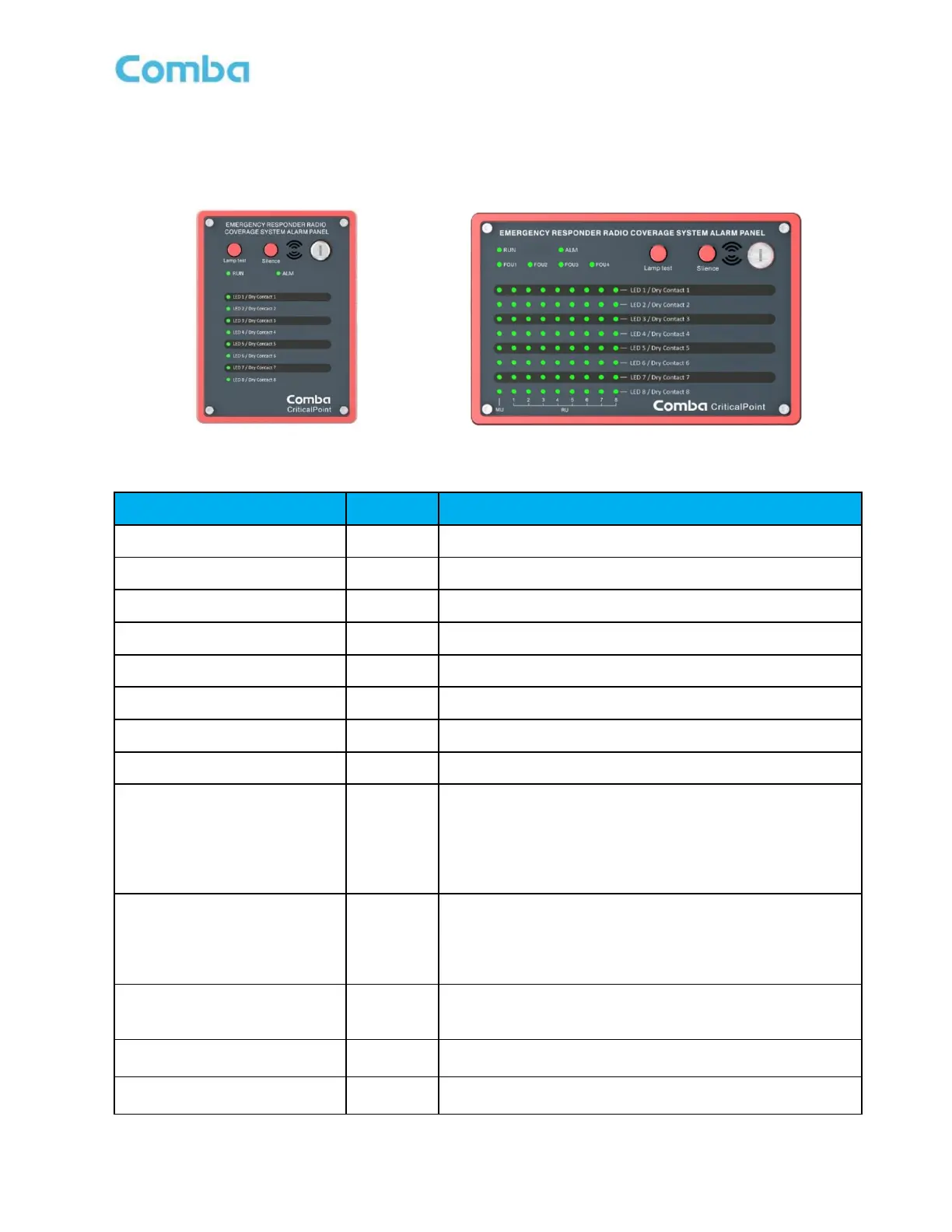
The V3 AP LED indicators help the user to check the equipment/system status quickly and easily. See below
Figure 180 and 181 as well as Table 29 and 30 which explain their operation.
Figure 180: V3 AP LED Status Indicators
Table 29: V3 AP LED Status Indicator General Explanation
Green=Normal; Red=Alarm (AC Power Alarm)
Alarm indicator. ON = alarm; OFF = no alarm.
Alarm indicator. ON = alarm; OFF = no alarm.
Alarm indicator. ON = alarm; OFF = no alarm.
Alarm indicator. ON = alarm; OFF = no alarm.
Alarm indicator. ON = alarm; OFF = no alarm.
Alarm indicator. ON = alarm; OFF = no alarm.
Alarm indicator. ON = alarm; OFF = no alarm.
Operation indicator.
1. OFF: MCU cannot be powered up
2. Solid RED: Software is not ready / cannot boot up
3. Solid Green: Software is running normally
4. Green (1 blink, pause): Not commissioned
5. Green (2 blink, pause): RR Switches are both off
Alarm indicator. ON = alarm; OFF = no alarm.
1. OFF: No Alarm
2. Solid Red: Dry Contact 1-8 active
3. Red (1 blink, pause): Any other alarms besides Dry
Contact configured alarms.
Indicates that the alarm display panel displays alarms for a
specific FOU.
*For APV3-DAS only
Press the lamp test button to perform a lamp self-check
when the key switch is on.
Mute button, which can turn off the buzzer sound when the
key switch is on