1.16 V3 BDA FUNCTIONAL BLOCK DIAGRAM
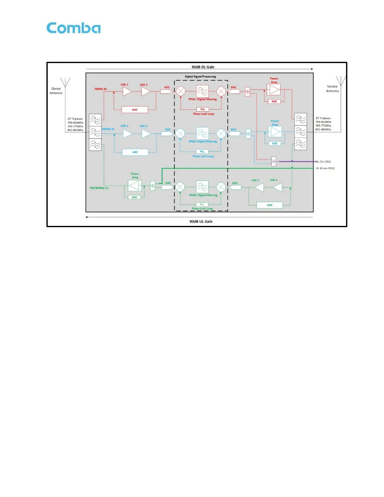
Figure 9: V3 BDA Functional Block Diagram
Note: The above block diagram shows the 700MHz DL path in red, the 800MHz DL path in Blue, the
700/800MHz combined DL path in purple, and the 700/800MHz combined UL path in green.
In the downlink path, RF signals are received by the donor antenna from the tower site and fed to the DT port
of the BDA. The DT Triplexer will allow only DL signals within the DL passband to enter the DL path of the BDA
and will reject all others. The DT Triplexer will also separate the 700MHz and 800MHz DL signals so they can
be conditioned separately. After the DT Triplexer, the signals enter the LNA modules for pre-amplification and
then pass to the digital RF integrated module for digital filtering and frequency conversion. Once the DL signals
have been digitally processed, they enter the DL PA for a final gain boost to amplify to final target power. After
amplification, the DL signals will enter the MT Triplexer for final combining/filtering, rejecting all wideband noise
from the DL PAs, and only passing the desired signals within the 700MHz and 800MHz DL passbands. The
DL signals are finally transmitted at the MT port towards service antenna(s). Additionally, when in a fiber DAS
configuration, DL signals are coupled internally before the DL PA to feed the DL FOU port which is used in
fiber DAS applications to feed the Fiber Optic Expansion Unit (FOU).
In the uplink path, the mobile RF signals from portable radios are received by the service antenna(s) and travel
through a network of passive devices before entering the BDA at the MT port. The MT Triplexer will allow only
UL signals within the UL passband to enter the UL path of the BDA and will reject all others. The MT Triplexer
does not separate the 700MHz and 800MHz signals in the UL path as the bands are directly adjacent to one
another. The 700MHz and 800MHz UL signals use the same amplification path. After the MT Triplexer, the
signals enter the LNA module for pre-amplification and then pass to the digital RF integrated module for digital
filtering and frequency conversion. Once the UL signals have been digitally processed, they enter the UL PA
for a final gain boost to amplify to final target power. After amplification, the UL signals will enter the DT Triplexer
for final filtering, rejecting all wideband noise from the UL PA, and only passing the desired signals within the
700MHz and 800MHz UL passbands. The UL signals are finally transmitted at the DT port towards the donor
antenna and to the PS radio site. Additionally, when in a fiber DAS configuration, UL signals received from the
Fiber Optic Expansion Unit (FOU) are fed into the BDA through the UL FOU port and coupled into the UL path
before the UL PA.