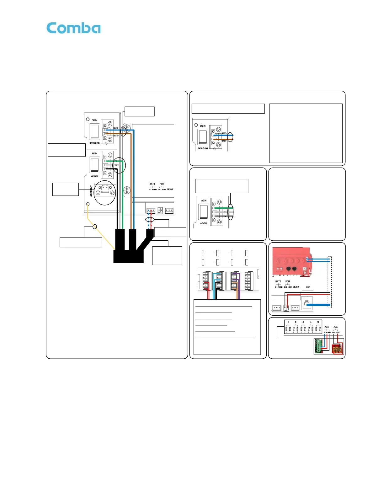
Connect to BBU V3
Power ON: Turn on DC switch to D C IN
Power OFF: Turn DC switch to BATT CHRG, t hen
switch off DC from BBU V2 or other DC source
*Turn OFF all switches before connection (switch to AC OFF and BATT CHR G)
Turning ON the system with AC and ba ttery installed:
1. Turn on AC Breaker in the BBU V3
2. Turn on the battery breaker in the BBU V3,
3. If battery LED is not lighted up, press the RESET button for <5s, r elease when LEDs starts blinking
4. Turn on AC Switch in the BDA V3
Turn On the system with AC only :
1. Turn on AC Breaker in the BBU V3
2. Turn on AC Switch in the BDA V3
Turn ON the system with battery only (when there is no AC):
1. Turn on the battery breaker in the BBU V3,
2. If battery LED is not lighted up, press t he RESET button for <5s, releas e when LEDs starts blinking
3. Turn on DC switch once (to DC IN th en to BATT CHRG) to turn up the system by batter y only
4. DC switch should stay on BATT CHRG side afterwards at all other times
Run on Battery:
1. Turn off AC switch i n t he BBU V3 or BDA V3
Turn OFF the system:
1. Turn off AC switch i n t he BBU V3 and BDA V3
2. Turn off the battery breaker
PE: Green/Yellow
N: White
L: Black
BATT-: Blue
BATT+: Brown
Copper Wire:
Connects to ground
B: Blue/White
A: Red/White
DC48V
OUTPUT
ONLY!!!
Power Cord
From BBU V3
DO NOT
CONNECT TO
<48VDC +/->
Connect to Comba BBU V2 / Other DC Source / 3
rd
Party BBU
Connect to AC Only
BATT-: BBU V2 Load- / DC- (GND)
BATT+: BBU V2 Load+ / DC+
PE: AC Source Ground
N: AC Source Neutral
L: AC Source Live
Power ON: AC IN
Power OFF: AC OFF
Alarm Connection Example:
BDA V3 + BBU V3 using NFPA 1221 2019
LOSS OF NORMAL AC POWER
(Dry Contact 2, RED, Normally Open)
BATTERY CHARGER FAILURE
(Dry Contact 3, BLUE, Normally Open)
LOW-BATTERY CAPACITY
(Dry Contact 4, BLACK, Normally Open)
DONOR ANTENNA MALFUNCTION
(Dry Contact 5, PURPLE, Normally Open)
ACTIVE RF-EMITTING DEVICE MALFUNCTION
(Dry Contact 6, ORANGE, Normally Open)
END OF LINE RESISTOR MAY BE
CONNECTED WITH CONDUCTORS TO FIRE ALARM
MONITORING MODULE
AP V1
Connection
External Alarm 1-5
- For external device Dry
Contact Alarms input
- DO NOT connect to
circuitry with voltage
#5 is BDA <Door Open>
Comba AP
CO M
CL OSE
OPEN
1
CO M
CL OSE
OPEN
2
CO M
CL OSE
OPEN
3
CO M
CL OSE
OPEN
4
CO M
CL OSE
OPEN
5
CO M
CL OSE
OPEN
6
CO M
CL OSE
OPEN
7
CO M
CL OSE
OPEN
8
DO Not Connect
both AC and DC
In this scenario
Switch to
AC OFF /
BATT CHRG
before connection
DO Not Connect
both AC and DC
In this scenario
Switch to
AC OFF /
BATT CHRG
before connection
FOU (DAS)
Connection
To First FOU
FOU UL1
FOU DL1
-
+
Reg ular ETH C able
Powering other devices:
There are 2 x 28VDC (when there is no
need for AP or FOU) and 1 x 48VDC
available for external devices.
Total Power Consumption including
BDA (100W max)/FOU (25W
max)/AP (3W) and all external
devices should be less than 205W.
All negative terminals from 48VDC
and 28VDC are tied to the ground.
Use only for +48V/+28VDC or
floating DC input devices. V3 DOES
NOT support -48V/-28VDC systems.
28VDC
+48V GND
FOU IN1
FOU AUX1
V1.1
20231208
Warning!
DO NOT use -48VDC power
source!
DC Source must be +48VDC or
Floating DC Output!
Highly recommend to measure
and confirm the power source
(including Comba equipment)
before the connection