1.18 V2 FOU FUNCTIONAL BLOCK DIAGRAM
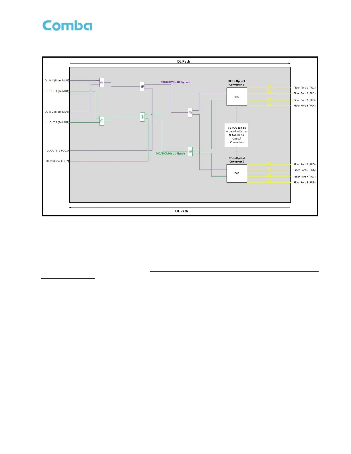
Figure 11: V2 FOU Functional Block Diagram
Note: The above block diagram shows the 700MHz DL path in red, the 800MHz DL path in Blue, the
700/800MHz combined DL path in purple, and the 700/800MHz combined UL path in green.
There are two DL IN and two UL OUT ports on the FOU. The purpose is to allow two BDA/MU’s to feed signals
to and from the FOU to provide redundancy. This redundancy functionality is not currently available but is
planned for release in the future. For now, always connect the BDA/MU FOU connections to the DL IN 1 and
UL OUT 1 FOU ports.
There is a DL OUT and UL IN (DL_E and UL_E) port on the FOU. These ports are used to interconnect to
additional FOU devices for further system expansion. You can daisy-chain up to 4 FOUs from a single BDA/MU.
Each FOU can be ordered/configured to have one or two RF-to-optical converters and can support 4 or 8 RUs.
Each RF-to-Optical converter module can support up to 4 RUs. A fully loaded system can support 32 RUs from
a single BDA/MU using 4 FOUs, each with 2 RF-to-Optical converters.
In the downlink path, the DL signals are received from the BDA/MU at the DL IN port of the FOU. Once the DL
signals enter the FOU from DL IN 1 and DL IN 2, they are combined and fed to the RF-to-Optical converter(s).
Once the DL signals reach the RF-to-Optical converters, they are converted from an RF signal to an optical
signal and transmitted down the fiber to be received by the RU.
In the uplink path, the UL optical signals received from the RUs are fed to the RF-to-Optical converter and
converted to an RF signal. The UL signals are then combined with UL Signals from other FOUs and fed towards
the FOU UL OUT ports. Finally, the UL signals are transmitted from the UL OUT ports towards the BDA/MU
FOU UL IN port.