CRITICALPOINT 700/800MHZ BDA/DAS/BBU V3 USER MANUAL
©2024 Comba Telecom. All Rights Reserved.
568 Gibraltar Drive, Milpitas, CA 95035 | +1 408 526 0180
Rev. 1-0-2 Rev. Date: 11-1-2024
6 ALARMS, TROUBLESHOOTING, AND MAINTENANCE
The V3 system alarms can be configured in many ways depending on the local code requirements. This
section of the user manual will provide an overview of the V3 system alarm operation, default alarm
configuration, alarm LED indicators, buzzer indicators, GUI alarm indicators and settings, alarm wiring, and
more.
6.1 V3 BDA/MU/RU LED INDICATORS, BUZZER, AND LAMP TEST
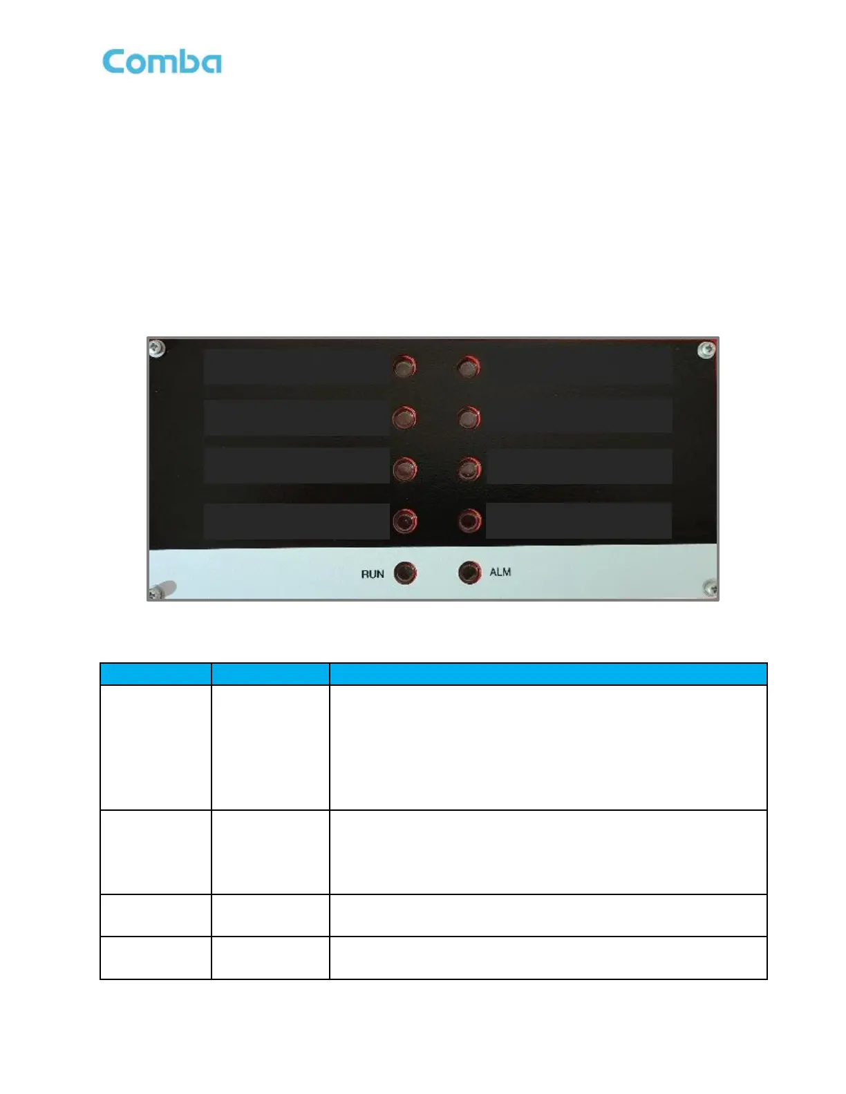
The BDA/MU/RU LED indicators help the user to check the equipment status quickly and easily. The LED
status indicators mirror the dry contact alarm outputs. See below Figure 172 and Table 25 which explain their
operation.
Figure 172: BDA/MU/RU LED Status Indicators
Table 25: BDA/MU/RU LED Status General Explanation
Operation Indicator.
OFF = MCU cannot be powered up.
Solid Red = Software is not ready / cannot boot up.
Solid Green = Software is normally running.
Green (1 blink, pause) = Not commissioned.
Green (2 blink, pause) = RF switches are both off.
Alarm Indicator.
OFF = No Alarm.
Solid RED = Dry Contact Alarms.
Red (1 blink, pause) = Any other alarms except Dry Contact Alarms.
Normal AC Power Indicator.
Green = Normal/No Alarm; OFF = NO AC Detected
Supervisory Alarm Indicator.
ON = alarm; OFF = No Alarm.