©2024 Comba Telecom. All Rights Reserved.
568 Gibraltar Drive, Milpitas, CA 95035 | +1 408 526 0180
2.21 V3 BDA/MU, V2 FOU, AND V3 RU RF AND FIBER WIRING
The RF and Fiber connections should be made before powering up the devices. The RF jumpers for BDA/MU
to FOU connections are provided with the V2 FOU. If the length of the provided jumpers is not sufficient, you
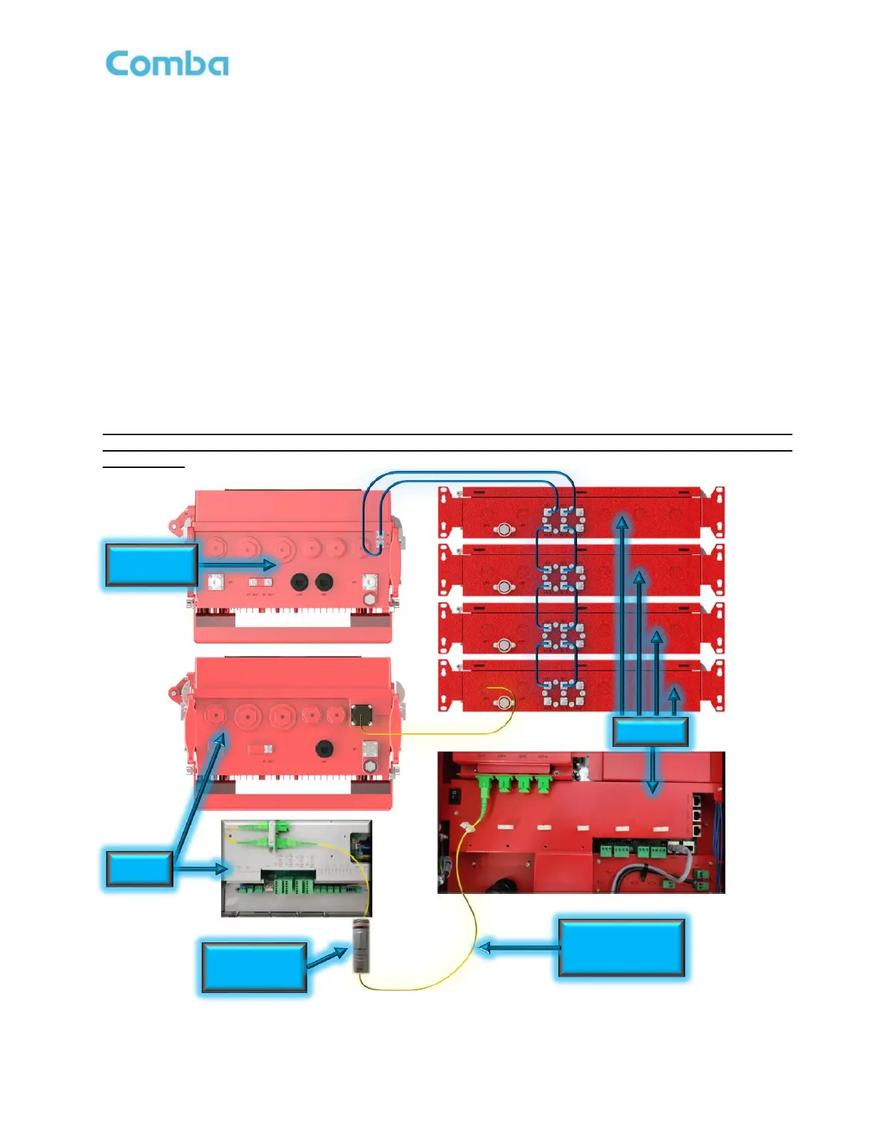
must source a cable of sufficient length from a third-party supplier. See Figure 55 below for RF and Fiber wiring.
Follow the below instructions to connect RF and Fiber Cables:
• Connect SMA Jumper from BDA/MU “UL” port to FOU “UL1” port.
• Connect SMA Jumper from BDA/MU “DL” port to FOU “DL1” port.
• If using more than one FOU, connect SMA Jumper from FOU(n) “UL_E” port to FOU(n+1) “UL1” port.
• If using more than one FOU, connect SMA Jumper from FOU(n) “DL_E” port to FOU(n+1) “DL1” port.
• Connect Single-Mode Fiber with SC-APC connector to FOU “OP1” Optical Port. Make the connection
through the provided fiber cable gland or a liquid tight conduit fitting.
• Connect Single-Mode Fiber with SC-APC connector to RU “OP1” Optical Port. Make the connection
through the provided fiber cable gland a liquid tight conduit fitting.
Note: Ensure Fiber is within performance specifications before making connections. For more
guidance on fiber requirements and recommended testing, see the technical application note in
Appendix L.
Figure 55: V3 BDA/MU, V2 FOU, and V3 RU RF and Fiber Wiring