3.30 COMMISSIONING – PARAMETER OPTIMIZATION
Optimizing Downlink in BDA Mode:
Downlink Channel Input (DL_IN), Target Power (DL_TAR), Downlink Gain (DL_GAIN) should be
already calculated. Ensure Main RF Switches and Channel RF Switches are turned ON.
For DL Input:
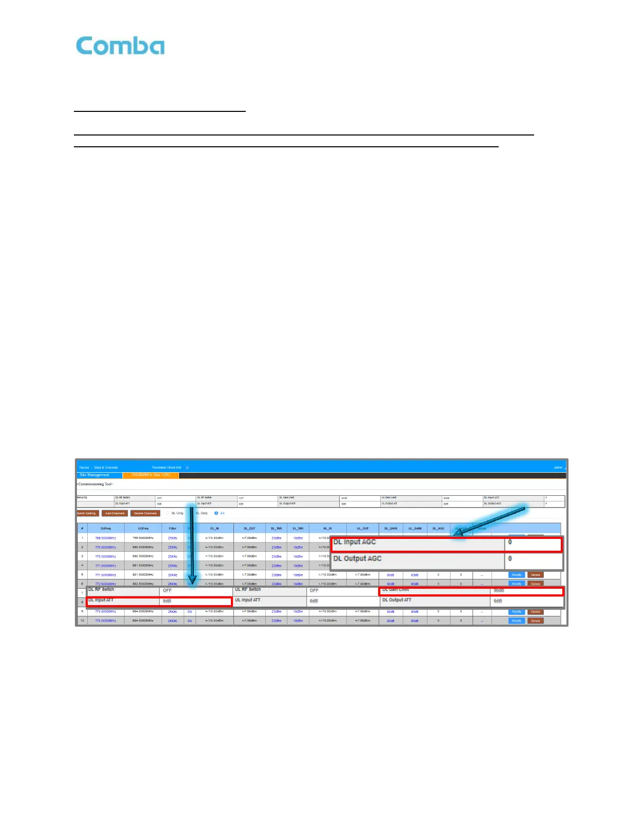
• Monitor <DL Input AGC>; Front-End Gain can be reduced by doing any of the following
a. Use DL Gain Limit, if total DL gain required can be 65dB or lower.
b. Use DL Input ATT, to reduce the DL Input AGC to be below 10dB, if total gain required is >65dB.
It is recommended to use only DL Input ATT or DL Gain Limit, but not both.
The purpose of mitigating DL Input AGC is to ensure you do not saturate the front-end receiver of the BDA
and keep the LNA in its linear range.
The current gain setting will change after modifying the Gain Limit or DL Input ATT, and the user must reset
the desired gain.
Example:
1. The original Filter’s DL Gain was set to 80dB for each filter.
2. DL Input AGC = 15dB; User decides to set 10dB of DL Input ATT.
3. Filter DL Gain is reduced to 70dB for each filter.
4. The user must Batch set Filter’s DL Gain back to 80dB.
In this example, essentially, 10dB attenuation is relocated from later stage (in FPGA) to the front end.
Figure 144: Optimizing BDA – DL Input ATT and DL Gain Limit
 Loading...