CRITICALPOINT 700/800MHZ BDA/DAS/BBU V3 USER MANUAL
©2024 Comba Telecom. All Rights Reserved.
568 Gibraltar Drive, Milpitas, CA 95035 | +1 408 526 0180
Rev. 1-0-2 Rev. Date: 11-1-2024
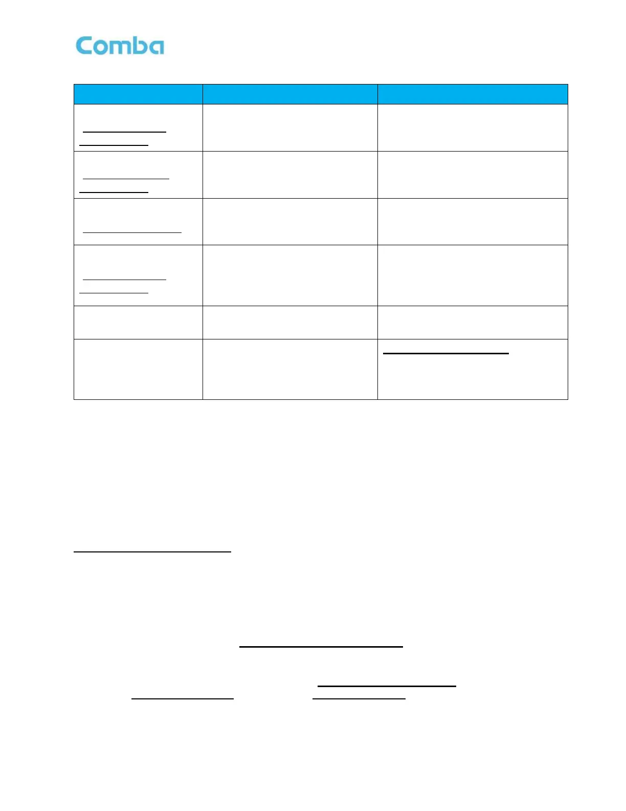
Table 19: Commissioning BDA – Power, Gain, Attenuation and AGC/ALC Controls
Input ATT
(Overview / Sites &
Channels page)
0–30dB range to reduce from Total
Gain* and reduce BDA Input Power.
This affects wideband gain.
Gain Limit
(Advanced / Sites &
Channels page)
Option to set Total Gain* to 65dB or
90dB. When 65dB is selected, the
BDA will bypass an input LNA.
When Input Power is high and
System requires 65dB gain or less.
DL_GAIN / UL_GAIN
(Site & Channels page)
Channel Gain Setting. 0-30dB
range below Total Gain. This is to
control gain for individual filters.
Use to set the gain for individual filters.
Output ATT
(Overview / Sites &
Channels page)
0-20dB range to reduce the Total
Gain* and reduce Target Channel
Output Power at the same time.
This affects wideband
When Output Power is high
When lower Output Broadband Noise
is desired (Near Donor Site).
DL_TAR / UL_TAR
(Site & Channels page)
Sets the output power limit for
individual filters.
Set to the target filter output power.
Target Composite
Output Power
(Overview page)
Limit the device’s composite output
power.
Not recommended to use. If the user
wants to reduce the composite output
power, use Output ATT or DL_TAR /
UL_TAR for better RF performance.
*Total Gain: the max gain that the system is configured to use. It is affected by the Input ATT, Gain Limit
and/or Output ATT.
Example:
The calculated DL Gain that is required is 50dB. The BDA DL_Gain only has a 30dB adjustment range and
the default MAX Gain setting is 90dB (Total Gain of 90dB). The user can only reduce the DL CH_Gain from
90dB to 60dB. Rather than using external attenuators to reduce the gain to 50dB, the user can adjust either
DL Input ATT, DL Output ATT, or DL Gain Limit (Bypass LNA) to reduce the Total Gain to 80dB or lower,
then use DL CH_Gain to adjust it to 50dB.
BDA Gain, Power, and AGC/ALC
Once a Target Channel Output Power and CH_Gain have been set, the AGC/ALC level will be set for the
channel filter. If input power is below a level in which the CH_Gain will amplify it to Target Channel Output
Power, gain will not be reduced by AGC/ALC. If the input power is above a level in which the CH_Gain will
amplify it above Target Channel Output Power, the AGC/ALC circuits will automatically reduce the gain to
reach the Target Channel Output Power.
• DL_IN: always indicates the channel power read from DT port, regardless of what the Gain Limit or
ATT settings in the system.
• DL_GAIN: the gain that will be applied to the input.
• The expected DL_OUT can be calculated as: DL_OUT = DL_IN + DL_GAIN
And if DL_OUT > DL_TAR, system will limit DL_OUT = DL_TAR.
The Gain Limit / ATT / Target Output Power will affect the max value for gain and/or DL_TAR that users can
set. See Figure 138 below which shows the <Sites & Channels> page and the RF parameters.
 Loading...