©2024 Comba Telecom. All Rights Reserved.
568 Gibraltar Drive, Milpitas, CA 95035 | +1 408 526 0180
Figure 138: Commissioning BDA – Power, Gain, and AGC/ALC
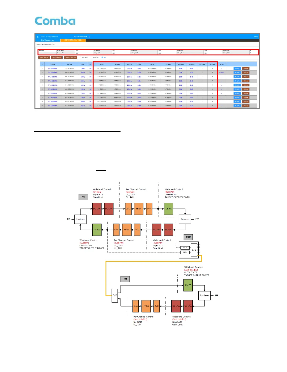
Fiber DAS Diagram and RF Parameters
The V3 Fiber DAS has multiple parameters to control the gain and power and provides AGC/ALC to limit the
output power. The Fiber DAS system structure and RF parameters are built based on the BDA. Refer to the
content from the previous section. See Figure 139 and Table 20 for a detailed description of the Fiber DAS
parameters.
Note: The diagram below is NOT depicting the actual block diagram of the system but is a simplified
diagram showing the approximate function of each parameter.
Figure 139: Commissioning Fiber DAS – Power, Gain, and Attenuation BDA Block Diagram