CRITICALPOINT 700/800MHZ BDA/DAS/BBU V3 USER MANUAL
©2024 Comba Telecom. All Rights Reserved.
568 Gibraltar Drive, Milpitas, CA 95035 | +1 408 526 0180
Rev. 1-0-2 Rev. Date: 11-1-2024
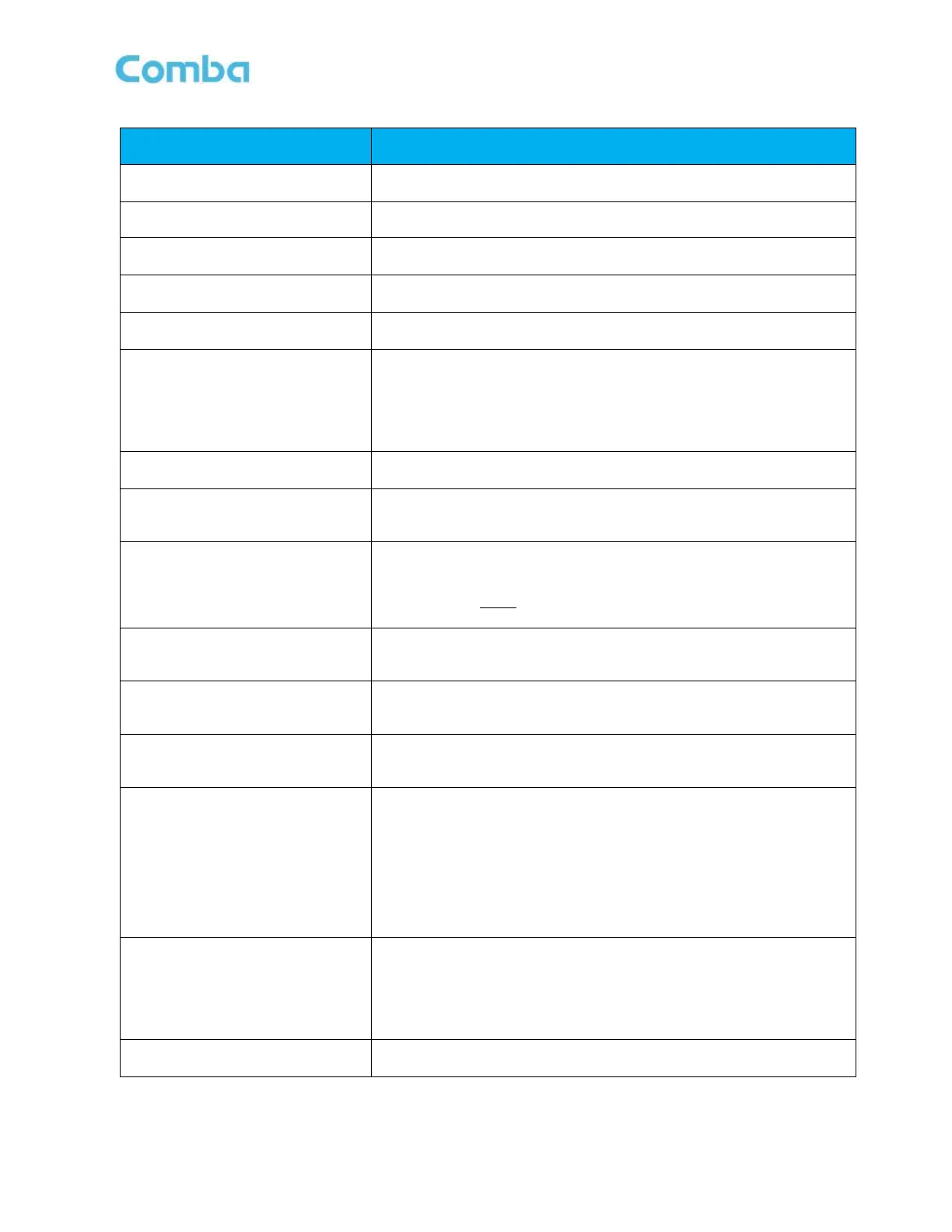
Table 13: V3 Fiber DAS Commissioning Procedure Tasks Explanation Option 2
1. Complete Pre-Commissioning
Tasks
⚫ Complete ALL pre-commissioning tasks. Refer to section 3.1
⚫ Start of the Commissioning Process
3. Wake Up All System BBU
Batteries
⚫ Wake up all the Batteries in the system for al BDA/MU, FOU, and RU
devices. Refer to section 3.6
4. Power ON All System Devices
⚫ Power ON the BDA/MU, FOUs, and RUs in the system. Refer to
section 3.9
5. Login to the BDA/MU web GUI
⚫ Using a laptop, login to the Graphical User Interface to program the
BDA/MU. Refer to section 3.10
6. Set BDA/MU General Information
and Alarms
⚫ User Management. Setup user accounts and permissions. Refer to
section 3.10
⚫ Set Device Information (name, location, Lat/Long, etc.). Refer to
section 3.16, 3.17, and 3.18
⚫ Setup Alarm Configuration. Refer to section 3.19
⚫ Setup Battery Backup Configuration. Refer to section 3.20
7. Detect Annunciator Panel(s)
⚫ Navigate to <Home – MU – AP > to detect the APs. Refer to section
3.21
8. Add Radio Tower Site(s) details in
<Device - Sites & Channels – Site
Management>
⚫ Add a radio site (Name, Address, System Type).
Note: If the system utilizes more than one radio site, the user can add
multiple sites. Refer to section 3.22
9. Setup Channel Filters/Sub-bands
for the Site(s)
⚫ Enter the total number of channels or number of sub-bands
⚫ Enter the frequency details for channel filters/sub-bands
⚫ Enter the digital filter BW for all the channels/sub-bands
⚫ Select the active control channel(s) in the description column
Refer to sections 3.22 and 3.23
10. Run Isolation Detection Process
⚫ Measures the isolation between the donor antenna and service
antenna branches. Users can use the onboard measurement tool or
enter a manual measurement. Refer to section 3.26
⚫ Measures the DL Input Power of the assigned Control Channel. Users
can use the onboard measurement tool or enter a manual
measurement. Refer to section 3.24
⚫ Measures the range of UL Input Power seen from portables within the
coverage area. Users can use the onboard measurement tool or enter
a manual measurement. Refer to section 3.25
13. Review GUI Recommendations
vs. Design
⚫ The commissioning guide will generate recommended DL/UL Target
Power and Gain settings based on the user inputs and results of the 3
commissioning tests. The commissioning guide recommended
settings should be compared to the system design parameters to
identify any inconsistencies that may require further troubleshooting.
⚫ If a user decides to use the recommended settings, the user will still
need to set all the Target Powers and Gains manually in the “Device”
pages.
Refer to Section 3.27
14. Set BDA/MU Target Power, Gain,
Squelch, and Advanced Features
⚫ Set the BDA DL and UL Channel Target Power
⚫ Set the DL and UL Gains
⚫ Set the DL and UL Squelch Thresholds
⚫ Turn ON NetProtect UL PA Muting, Oscillation Detection, and Donor
Disconnection Detection.
Refer to sections 3.28 through 3.36
15. Change the BDA/MU Device Type
to DAS
⚫ Navigate to <Management - Device Information> section to change
the Device Type from BDA to DAS. Refer to section 3.13