When using the platform of products in a Fiber DAS configuration, The BDA/MU will interface with the FOU(s)
to expand to feed a system of up to 32 RU’s. The FOU connects to the BDA/MU using 2 SMA style coax
jumpers (one for DL and one for UL), a DC Power Cable, and an ethernet RJ45 cable for RS485
communications. Each FOU can support either 4 or 8 RU’s. Each BDA/MU can support feeding up to 4 FOUs.
This means a fully loaded system using 1 BDA/MU and 4 FOUs can feed up to 32 RUs from a single donor
antenna. The FOUs main function is to convert the RF signals to Optical signals and vice versa in the reverse
path such that they can be transmitted over a long distance and recovered. The FOU interfaces to each RU
using a single strand of single-mode fiber using wave-division multiplexing (WDM) technology. The maximum
fiber loss that can be tolerated between the FOU and RU is 6.5dBo and the reflectance must be -60dB or lower.
Fiber losses exceeding 6.5dBo and/or having a reflectance higher than -60dB can cause communication and
RF performance degradation and/or complete failure of the fiber link.
The RU is a fiber-fed type of BDA which receives the optical signals in the DL, converts them back to RF and
provides final DL amplification and transmission onto the service antenna network. In the uplink path it receives
UL signals, conditions them, and then converts them to Optical signals to be transmitted to the FOU. Each RU
provides coverage to a different zone of a project and connects to its own indoor antenna network.
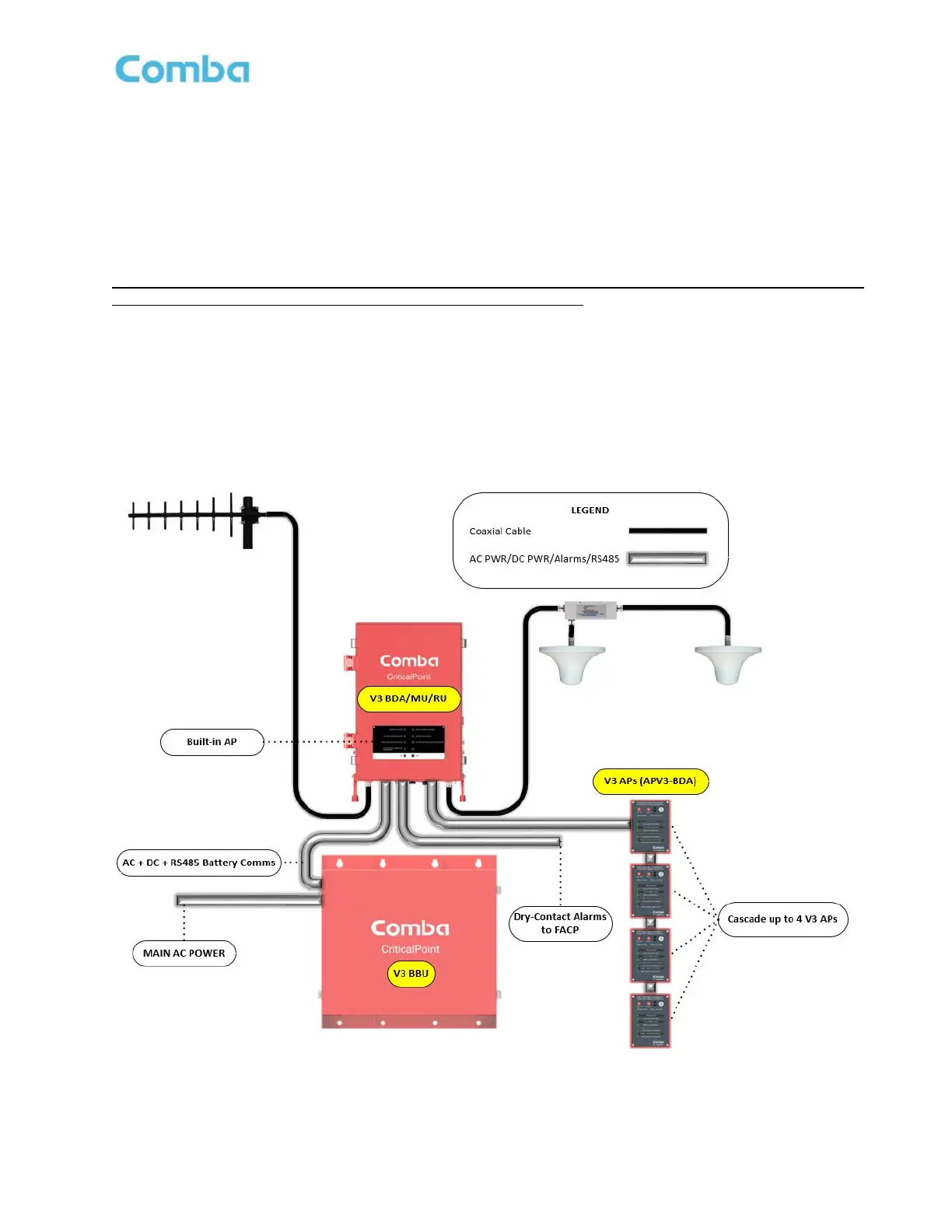
Figures 1 and 2 below show the system diagrams for a BDA/BBU system and a Fiber DAS system respectively.
Figure 1: V3 BDA/BBU with V3 AP High-Level System Diagram


 To Next Page