CRITICALPOINT 700/800MHZ BDA/DAS/BBU V3 USER MANUAL
©2024 Comba Telecom. All Rights Reserved.
568 Gibraltar Drive, Milpitas, CA 95035 | +1 408 526 0180
Rev. 1-0-2 Rev. Date: 11-1-2024
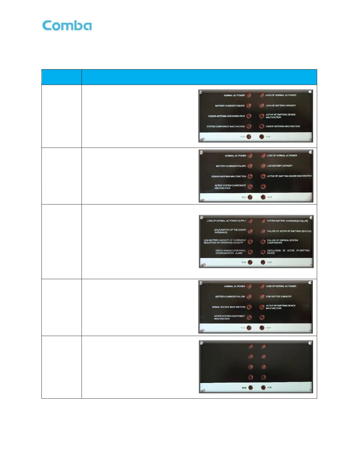
See Table 6 below for details about the annunciator front plate options and alarm configurations.
Table 6: V3 BDA/MU/RU Annunciator Front Plate Options
1. AC Input Normal
2. Loss of Normal AC Power
3. Loss of Battery Capacity
4. Battery Charger Failure
5. Active RF Emitting Device Malfunction
6. Donor Antenna Malfunction
7. System Component Malfunction
8. Donor Antenna Disconnection
9. RUN
10. ALM
1. Normal AC Power
2. Loss of Normal AC Power
3. Battery Charger Failure
4. Low-Battery Capacity
5. Donor Antenna Malfunction
6. Active RF-Emitting Device Malfunction
7. Active System Component Malfunction
8. RUN
9. ALM
1. Loss of Normal AC Power Supply
2. System Battery Charger(s) Failure
3. Malfunction of the Donor Antenna(s)
4. Failure of Active RF-Emitting Device(s)
5. Low-Battery Capacity at 70% Reduction
of Operating Capacity
6. Failure of Critical System Components
7. ERRCS Annunciator Panel
Communication Alarm
8. Oscillation of Active RF-Emitting Device
9. RUN
10. ALM
1. Normal AC Power
2. Loss of Normal AC Power
3. Battery-Charger Failure
4. Low-Battery Capacity
5. Signal Source Malfunction
6. Active RF-Emitting Device Malfunction
7. Active System Component Failure
8. RUN
9. ALM
1. Blank
2. Blank
3. Blank
4. Blank
5. Blank
6. Blank
7. Blank
8. Blank
9. RUN
10. ALM
 Loading...