©2025 Copeland LP.
026-1803 R13 Supervisor I&O User Guide 9 - 11
9.7.4 Hardware Overview
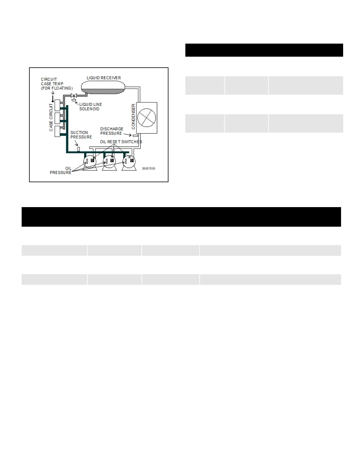
An overview of the input and output devices that make up a
Suction Group is shown in Figure 9-2. These devices should
be wired to input and output boards in the manner outlined in
Table 9-9 and Table 9-10.
9.8 Suction Float
The Floating Setpoint strategy within the Supervisor provides
a method for varying the suction setpoint of the group based
on the temperature within a circuit. When Floating Setpoint
Control is enabled, the Supervisor monitors either a circuit
temperature or a case temperature and adjusts the suction
setpoint if the temperature is too low or too high. The user
establishes a range outside of which the Supervisor is
instructed to make a one PSI adjustment to the suction
pressure setpoint to either reduce or increase the case
temperature. If the temperature continues to remain outside
of the range for a user-defined period of time, the Supervisor
continues to make pressure setpoint adjustments until the
temperature is within the established range. By varying the
suction pressure setpoint to match the temperature
requirements of the circuit, the Supervisor is able to ensure
product integrity while achieving maximum rack efficiency.
9.9 Analog Sensor Control
The Analog Sensor Control reads the values from one or
more analog sensors, compares them to a set of Cut In/Cut
Out setpoints, and operates a digital output (such as a relay)
based on the analog input in relation to the setpoints.
An Analog Sensor Control module performs three functions:
• COMBINER - Up to four analog inputs are combined into
a single analog value.
• CUT IN/CUT OUT CONTROL - The combined input
value is compared to a Cut In/Cut Out setpoint. Based on
this comparison, a digital output will be turned ON or
OFF.
• ALARMING - Alarms and notices can be generated
based on the combined value of the inputs and its
relation to a set of high and low alarm and notice
setpoints.
Figure 9-2 - Diagram of a Suction Group
Table 9-9 - Suction Group Inputs
Input Sensor Type Wiring Instructions
Suction
Pressure
100 lb. Eclipse
transducer
(see
Table 9-1 on page 9-
1
)
Discharge
Pressure
500 lb. Eclipse
transducer
(see Table 9-1 on page 9-
1
)
Oil Pressure
200 lb. Eclipse
transducer
(see
Table 9-1 on page 9-
1
)
Case Circuit
Temperature
Temperature
(see Table 9-1 on page 9-
1
)
Oil Reset
Switches
Digital
(see
Table 9-1 on page 9-
1
)
Table 9-10 - Suction Group Outputs
Output Device
Wire Output Board
Contacts to:
Set Failsafe Dip
Switch to:
Notes
Compressor N.C. N.C. (up) If you want a compressor to be OFF during network/power
loss, use N.O. fail-safes instead.
Unloader N.C. N.O. (down) These fail-safe settings are specifically for unloaders.
Liquid Line Solenoid
(LLS)
N.C. N.C. (up) Keeps solenoid energized during network/power loss.
Electric Defrost N.O. N.O. (down) Keeps contacts de-energized during network/power loss.