©2025 Copeland LP.
026-1803 R13 Supervisor I&O User Guide 2 - 2
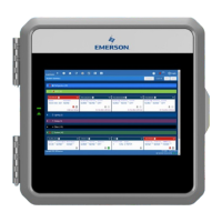
2.3 Plug-In Digital I/O Card
(P/N 537-4880)
This card adds two user-programmable digital outputs and
two digital inputs to enable connection of switches and
relays (relay contacts are rated at 3A up to 24 VAC).
The plug-in Digital I/O Network card connects to the power
interface board to the right of the two fixed RS485 I/O
Network connectors.
2.3.1 LED’s
The plug-in Digital I/O Network card LEDs can be used to
determine the status of normal operating parameters for the
card.
2.4 Wiring
1. Connect the RS485 Communication wire to the terminal
block headers as shown. The Cables are numbered 1
through 4.
2. Connect the 2-pin 7.5mm power connector and Ground
wire as shown in Figure 2-7
3. Connect the other end of the power cable to one of the
50VA P/N 640-0040 transformers.
4. Plug the 50VA P/N 640-0040 Transformers into a 120VAC
outlet.
5. Turn the power switch “On”. The unit should boot up to
the home screen.
6. You can log into the unit the first time by using the below
username and password if needed.
• Username = user
• Password = pass
7. Once logged in, you will be prompted to change your
password.
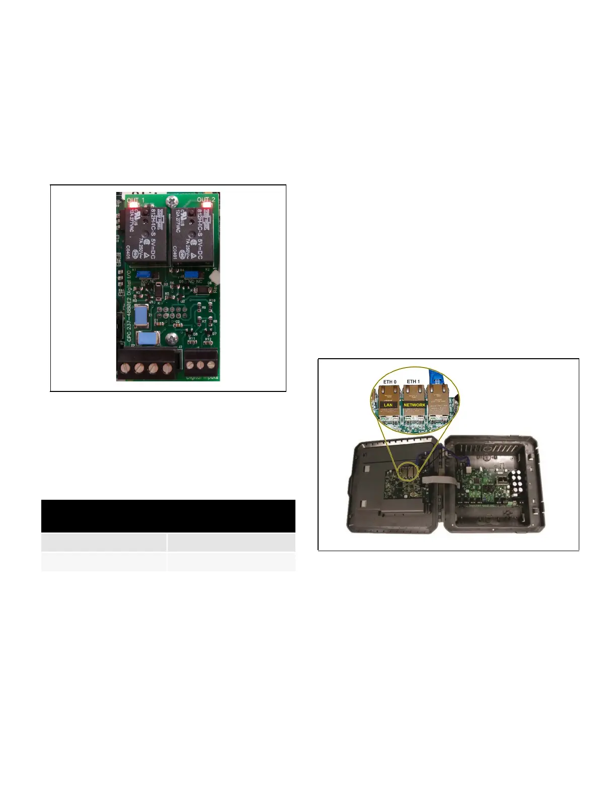
2.5 Ethernet Connections
1. ETH 0 is used to connect to corporate LAN.
2. ETH 1 is designed to be used for directly connecting to
PIB and laptop or PC and network devices. The default IP
for ETH 1 is 192.168.1.250
Note: When using an E3 Supervisory Controller with
RS485 COM A and COM B Ports, ONLY the COM A port
can be used for BACnet MSTP; the COM B port connector
MUST remain unused for BACnet MSTP Networks. This is
due to BACnet MSTP being a token passing network and
all devices must be on the same physical network cable
segment for successful token creation and passing.
Figure 2-2 - Digital I/O Card
Table 2-4 - LED Status for Plug-In Digital I/O Card
Plug-In Digital I/O Card
LEDs
Status
Red D1 (Out 1) ON: Relay Output 1 is On
Red D4 (Out 2) ON: Relay Output 2 is On
Figure 2-3 - E3 and Ethernet Connection