©2025 Copeland LP.
026-1803 R13 Supervisor I&O User Guide 2 - 3
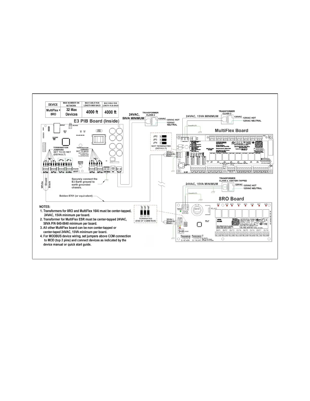
2.6 E3 RS485 Wiring Guide Example
• For E3 Serial IO Net connections, connect the white wire to the positive terminal and the back wire to the negative
terminal.
• For 8RO and MultiFlex RS485 IO Net connections, connect the white wire to the positive terminal and the black wire to the
negative terminal.
• Connect the shield wire to earth/chassis at the end of the IO Net (network) segment. Connect the shield wire to the center
terminal (0V) of the IO Net connector on the E3.
• For daisy-chain configurations, terminate devices at the beginning and the end of the network segment.
• All other devices in the network segment are not terminated (termination jumpers in the not-terminated position).
Figure 2-4 - E3, MultiFlex, and 8RO Wiring Layout