©2025 Copeland LP.
026-1803 R13 Supervisor I&O User Guide 3 - 7
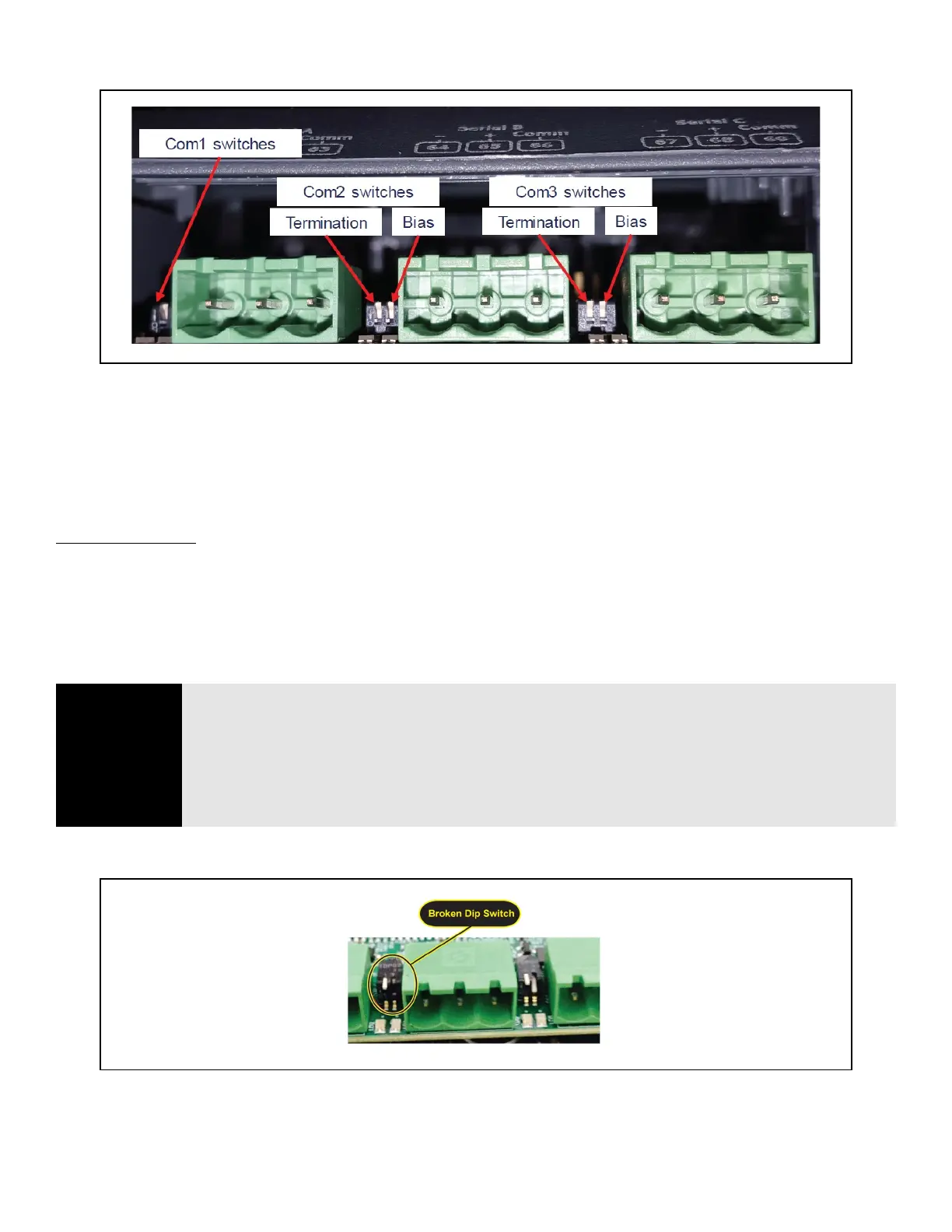
3.6.5 Dip Switch Termination and Biasing
The termination and biasing dip switches are located to the left of their respective communications port connectors. The
switches are oriented such that switch down is ON for the function. The dip switches are of the “piano key” type and must be
moved up and down when they are viewed as shown above.
The termination dip switch must be ON (down) when the Site Supervisor is the first or last device on the RS485 network, most
easily recognized by having only 1 Belden style cable attached to the connector.
What is biasing?
The transmission line into the RS-485 serial port enters an indeterminate state when it is not being transmitted to. This
indeterminate state can cause the receivers to receive invalid data bits from the noise picked up on the cable.
*
To prevent this,
set the bias dip switch to ON (down) which will add the appropriate amount of resistance.
*
Source: National Instruments Serial Troubleshooting Wizard
Figure 3-10 - Dip Switch Configuration
NOTE
The switches are somewhat fragile and care should be taken when switching them from ON to
OFF or vice versa. It is also likely that a small control screwdriver needs to be used because of
space and clearance between the COM port connectors, and you must ensure that power to the
controller is secured prior to changing the switch position(s). It is highly recommended that the
controller be removed from its enclosure or panel (if installed) so that ample light and line of
sight can be obtained during this procedure. An example of a broken dip switch can be seen
below.
Figure 3-11 - Broken Dip Switch