©2025 Copeland LP.
026-1803 R13 Supervisor I&O User Guide 9 - 30
9.16.3.4 Demand Limit Exceeded Alarm
The application provides an application alarm to signal a high
demand. The demand alarm limit and alarm delay will be
configurable.
The demand alarm delay is the amount of time the
application waits after the Shed Output turns on before the
demand alarm is generated. When the Shed Output turns off,
the demand alarm will return to normal.
9.16.3.5 Time In Shed Output
The application provides a Time In Shed output that
indicates the total time that the Shed Output has been on.
This output resets to zero every day at 00:00 hours.
9.17 Onboard I/O
Most of the general purpose input and output
communications devices required by the Supervisory
Controller to control refrigeration systems are connected to
the controller via the I/O Network. The I/O Network is a simple
RS485 three-wire connection that allows data interchange
between input boards (which read sensor values and digital
closures), output boards (which carry out commands from
the controller), and the controller.
The Supervisory Controller has the onboard inputs and
outputs which are initially supported by the controller.
Pulsing logic is now supported. When selecting Digital, the
relay works as normal. When Pulse is selected, relay pulsing
logic is applied. The relay will cycle periodically (turns ON and
keeps ON for a specified period of time), and the CfgRL0x
Period; CfgRL0x_OnTime parameters become available.
For the CfgRL01 OnTime parameter, when Pulse is selected,
this parameter specifies the duty cycle (the ON percentage of
the cycle period with a range from 0 to 100%).
For the CfgRL01 Period parameter, when Pulse is selected,
this parameter specifies the entire cycle period.
9.17.1 Licensing
The number of Onboard I/O applications allowed is based on the total number of applications allowed on the Supervisory
Controller platforms. Additional applications may be added with a separate license key.
9.17.2 Adding and Deleting Onboard I/O Application
The Onboard I/O application is initially installed by the system. The user is not able to add or delete it.
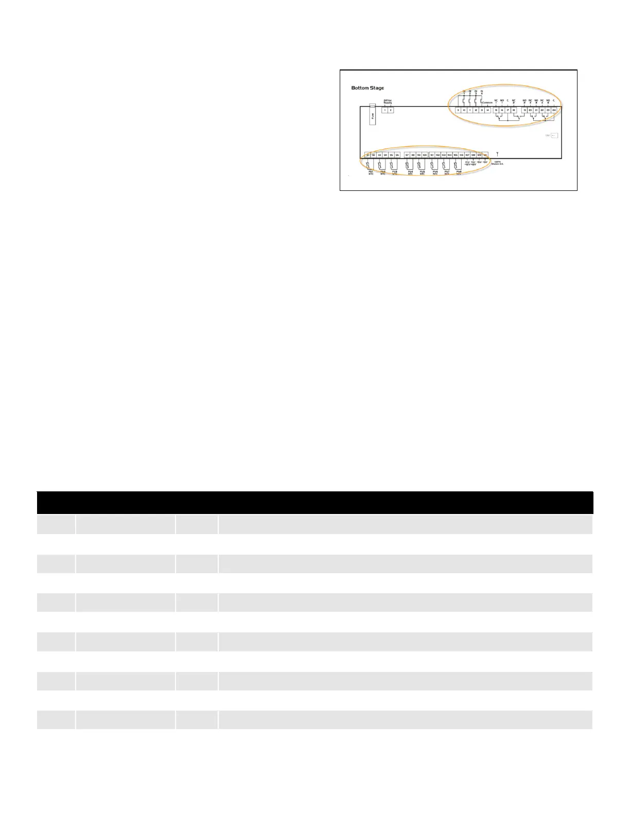
Figure 9-3 - Onboard Inputs and Outputs
Table 9-11 - Size and Limits of the Inputs and Outputs
Description Size Limits
0 Conf Probe 1 4 bit ntc(0) - Ptc(1) - 2/20mA(2) - 4/20mA(3) - 0/10V(4) - 0/1V(5) - 0/5V(6) - DIG(7)-e_ntc(8)
1 Conf Probe 2 4 bit ntc(0) - Ptc(1) - 2/20mA(2) - 4/20mA(3) - 0/10V(4) - 0/1V(5) - 0/5V(6) - DIG(7)-e_ntc(8)
2 Conf Probe 3 4 bit ntc(0) - Ptc(1) - 2/20mA(2) - 4/20mA(3) - 0/10V(4) - 0/1V(5) - 0/5V(6) - DIG(7)-e_ntc(8)
3 Conf Probe 4 4 bit ntc(0) - Ptc(1) - 2/20mA(2) - 4/20mA(3) - 0/10V(4) - 0/1V(5) - 0/5V(6) - DIG(7)-e_ntc(8)
4 Conf Probe 5 4 bit ntc(0) - Ptc(1) - 2/20mA(2) - 4/20mA(3) - 0/10V(4) - 0/1V(5) - 0/5V(6) - DIG(7)-e_ntc(8)
5 Conf Probe 6 4 bit ntc(0) - Ptc(1) - 2/20mA(2) - 4/20mA(3) - 0/10V(4) - 0/1V(5) - 0/5V(6) - DIG(7)-e_ntc(8)
6 Conf Probe 7 4 bit ntc(0) - Ptc(1) - 2/20mA(2) - 4/20mA(3) - 0/10V(4) - 0/1V(5) - 0/5V(6) - DIG(7)-e_ntc(8)
7 Conf Probe 8 4 bit ntc(0) - Ptc(1) - 2/20mA(2) - 4/20mA(3) - 0/10V(4) - 0/1V(5) - 0/5V(6) - DIG(7)-e_ntc(8)
8 Conf DI1 4 bit Normal DI (0) - Pulse Counter (1)
9 Conf DI2 4 bit Normal DI (0) - Pulse Counter (1)
10 Conf DI3 4 bit Normal DI (0) - Pulse Counter (1)
11 Conf DI4 4 bit Normal DI (0) - Pulse Counter (1)