©2025 Copeland LP.
026-1803 R13 Supervisor I&O User Guide 7 - 11
The wireless module has three inputs where temp sensors
can be connected. The module transmits to the gateway,
which is connected to the Supervisory Controller via I/O net.
The Gateway communicates to the Supervisory Controller
over the I/O network. During commissioning and installation,
the hand-held (HHT) must be used to address each wireless
node. The address appears as an I/O point just like a 16AI
MultiFlex board (address 1-16). If there are more than 16
modules, the other 16AI board application must be set up to
address the next 16 modules. The HHT is also needed in
order to make any changes.
For more information on Wireless Module System, refer to the
026-1734 User Manual.
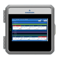
The Wireless Module is an enclosure with a built-in broadcast
antenna. This module may be mounted on a refrigerated
case, as long as it is within 100 feet clear line-of-site of a
Wireless Gateway. Obstructions like walls and doors will
reduce range. The module is primarily powered with a solar
cell, but it also has battery backup. The user can use an
external 5VDC supply if mounted in dark areas.
Table 7-6 lists all Wireless Modules along with their
characteristics for US and Canada only (902 MHz).
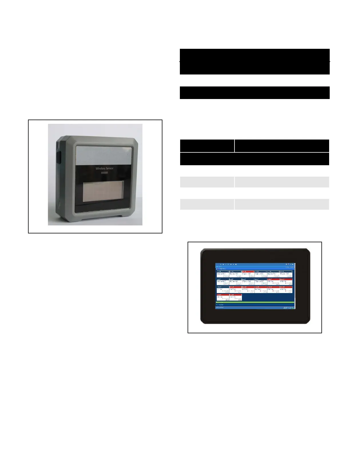
7.2.15 Site Supervisor Displays
See Section 8,Site Supervisor Displays for more information.
The Site Supervisor Display (P/N 818-7240) is a remote UI for
the Site Supervisor Display that connects to the controller. For
Site Supervisor Display 15.6 Inch and 21.5 Inch Display
information, see Section 8,Site Supervisor Displays.
Figure 7-17 - Wireless Module P/N 814-36xx
Table 7-6 - Wireless Standard Modules for US and Canada
Part Number Description
Modules for US and Canada
814-3600 User Selected inputs
Standard Modules
814-3653 Molex plug for 3 Std ERS 10K temp
sensor + clean mode
Table 7-7 - High Temp, Digital, and Humidity Modules for US and
Canada
Part Number Description
Modules for US and Canada
Digital Modules
814-3623 3 Digital + clean mode
Humidity Modules
814-3633 3 Humidity + clean mode
Figure 7-18 - Supervisory Controller Display