©2025 Copeland LP.
026-1803 R13 Supervisor I&O User Guide 9 - 50
Variable-speed fans simply use the percentage to determine
the fan speed. Thus, a 51% PID percentage will result in the
fan running at 51% maximum speed.
VS-SS combined fan setup is for the combination of a
variable-speed fan with single-speed fans. As PID increases
from 0% to the minimum VS%, the fans will stage ON, and the
VS% output will be at a minimum %. When PID reaches the
minimum VS%, all defined fan stages will be ON. As PID rises
from minimum VS% to 100%, the VS% output will match the
PID output.
9.36.3 Condenser Split Mode
The Supervisory Controller is capable of operating
condensers in a special mode that reduces its condensing
capacity. This special mode is called split mode.
Split mode is most often used in cold climates during periods
of low outside air temperature. Split mode is also sometimes
used when heated refrigerant from the refrigeration system is
being used as reclaim heat by an HVAC unit.
The most common way the Supervisory Controller achieves
split mode in an air-cooled condenser with single-speed fans
is to lock OFF 50% of the total number of fans. You may
choose to lock OFF all odd-numbered fans, even-numbered
fans, the first half of all fans, or the last half of all fans.
Split mode can also be achieved by activating a valve that
bypasses a portion of the tubing in the condenser manifold.
The resulting decrease in surface area results in reduced
cooling.
9.36.4 Fast Recovery
Under certain conditions the system pressure may increase
too quickly above the condenser setpoint to be reduced
effectively by normal condenser control. The Supervisory
Controller provides a user-definable fast recovery rate
setpoint at which all the condenser fans are turned ON to
reduce systembpressure.
For air-cooled and temperature-differential condenser
strategies, discharge pressure is always used as the control
value that determines fast recovery. You may choose to
enable or disable fast recovery, and also to include a delay
when transitioning from one mode to the other.
For evaporative condensers, up to 16 “override” temperature
sensors may be combined to yield a single override value that
is used for fast recovery. Fast Recovery is always used in an
evaporative condenser.
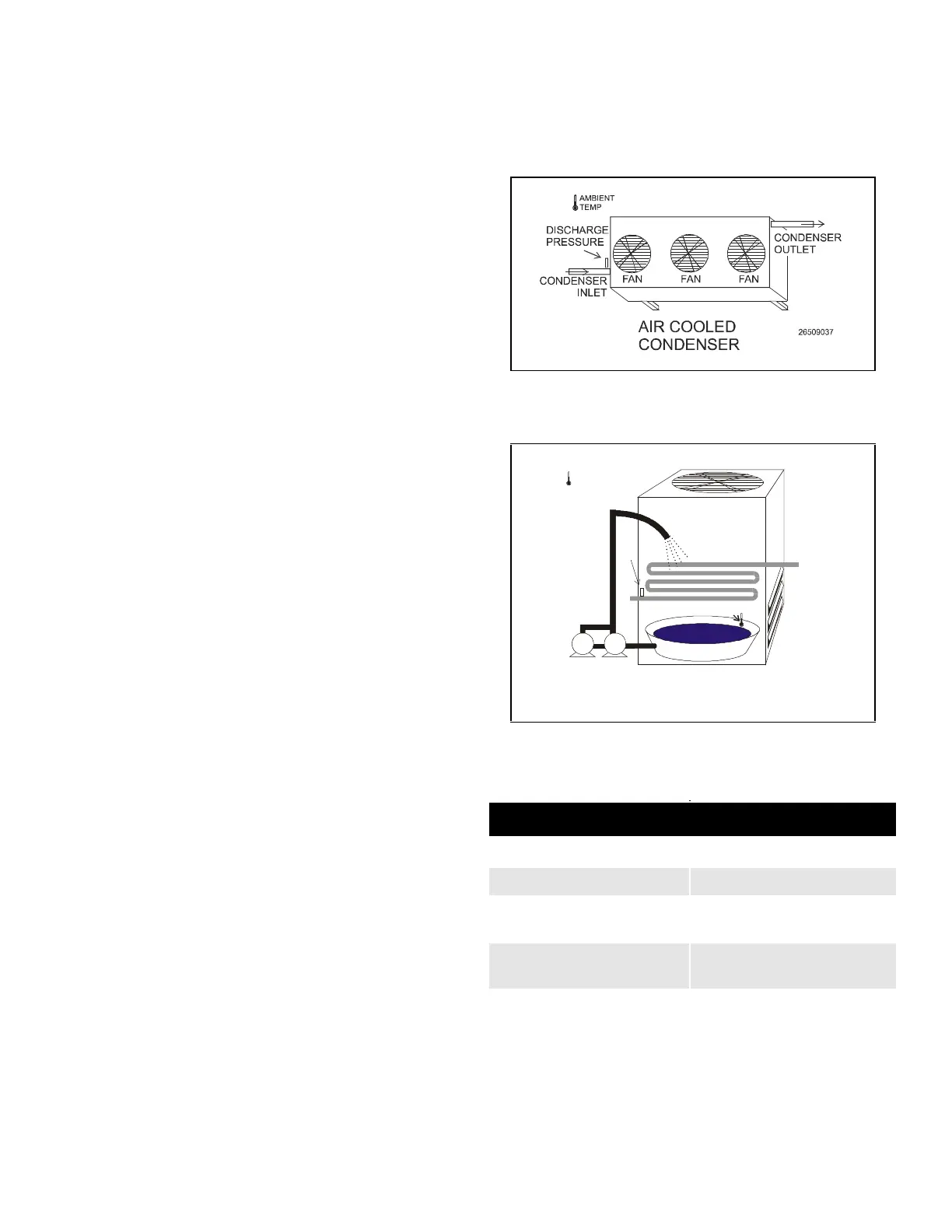
9.36.5 Hardware Overview
An overview of the input and output devices that make up a
typical Condenser Control application is shown by shows the
typical layout of an air-cooled condenser. shows the typical
layout of an evaporative condenser.
Figure 9-23 - Air Cooled Condenser Diagram
Figure 9-24 - Evaporative Condenser Diagram
Input Sensor Type
Discharge Pressure 500 lb. Eclipse transducer
Ambient Temp Temperature
Water Sump Temp
(Evap. only)
Temperature (Immersion)
Override Temp Sensors
(Evap. only)
Temperature
(Pipe-Mount)
EVAPORATIVE
CONDENSER
PUMP 2PUMP 1
WATER
SPRAY
FAN
INLET
DAMPERS
DISCHARGE
PRESSURE
COIL
WATER SU MP
TEMPERATURE
26509038
AMBIENT
TEMP
W
A
T
E
R
S
U
M
P