©2025 Copeland LP.
026-1803 R13 Supervisor I&O User Guide 3 - 13
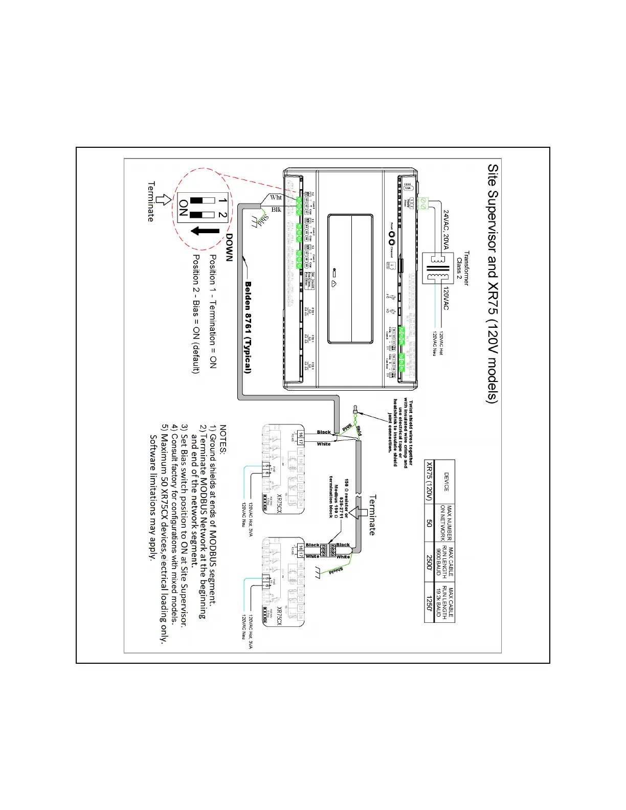
• Site Supervisor and XR75CX share the same MODBUS network polarity. Do not reverse polarity.
• Connect the shield wire to earth/chassis at the Site Supervisor end of the MODBUS network segment. Do not connect the
shield wire to any connector on the Site Supervisor or XR75CX.
• For daisy-chain configurations, terminate devices at the beginning and the end of the network segment. Set the dip switch
position 1 and 2 to the ON position on Site Supervisor. For XR75CX end of network, terminate with a
150-ohm resistor or 535-2711 termination block. All other devices in the network segment are not terminated.
Figure 3-19 - Supervisory Controller and XR75CX Wiring