Link Aggregation Control Protocol (LACP) | 293
In Figure 16-6, LAGs 1 and 2 have been placed into to the same failover group.
Figure 16-6. Configuring Shared LAG State Tracking
To view the failover group configuration, use the show running-configuration po-failover-group command
(Figure 16-7).
Figure 16-7. Viewing Shared LAG State Tracking in the Running-configuration
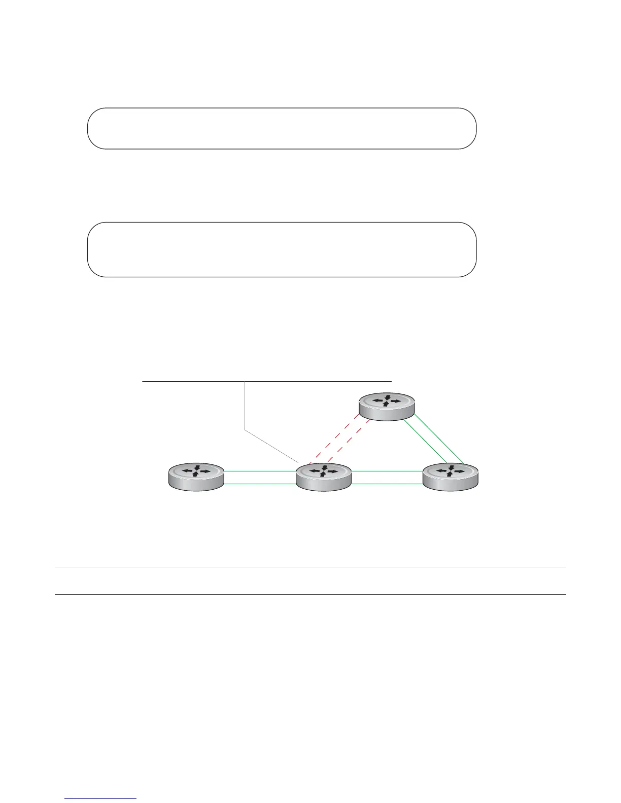
In Figure 16-8, LAGs 1 and 2 are members of a failover group. LAG 1 fails and LAG 2 is brought down
upon the failure. This effect is logged by Message 1, in which a console message declares both LAGs
down at the same time.
Figure 16-8. Shared LAG State Tracking
Message 1 Shared LAG State Tracking Console Message
May 16 06:19:37: %STKUNIT0-M:CP %IFMGR-5-OSTATE_DN: Changed interface state to down: Po 1
May 16 06:19:37: %STKUNIT0-M:CP %IFMGR-5-OSTATE_DN: Changed interface state to down: Po 2
FTOS#config
FTOS(conf)#port-channel failover-group
FTOS(conf-po-failover-grp)#group 1 port-channel 1 port-channel 2
FTOS#show running-config po-failover-group
!
port-channel failover-group
group 1 port-channel 1 port-channel 2
Po 1
Po 2
fnC0049mp
R1
R2 R3
R4
R2(conf)# port-channel failover-group
R2(conf-po-failover-grp)# group 1 port-channel 1 port-channel 2

 Loading...


