EasyManuals Logo

Dell Force10 MXL Blade Configuration Guide

Dell Force10 MXL Blade
690 pages
To Next Page IconTo Next Page
To Previous Page IconTo Previous Page
Page #553 background imageLoading...
Page #553 background image
Stacking | 551
Stack Group/Port Numbers
By default, each switch in Standalone mode is numbered stack-unit 0. Stack-unit numbers are assigned to
member switches when the stack comes up. Figure 31-5 shows the stack-group numbers of 40GbE ports on
an MXL 10/40GbE Switch.
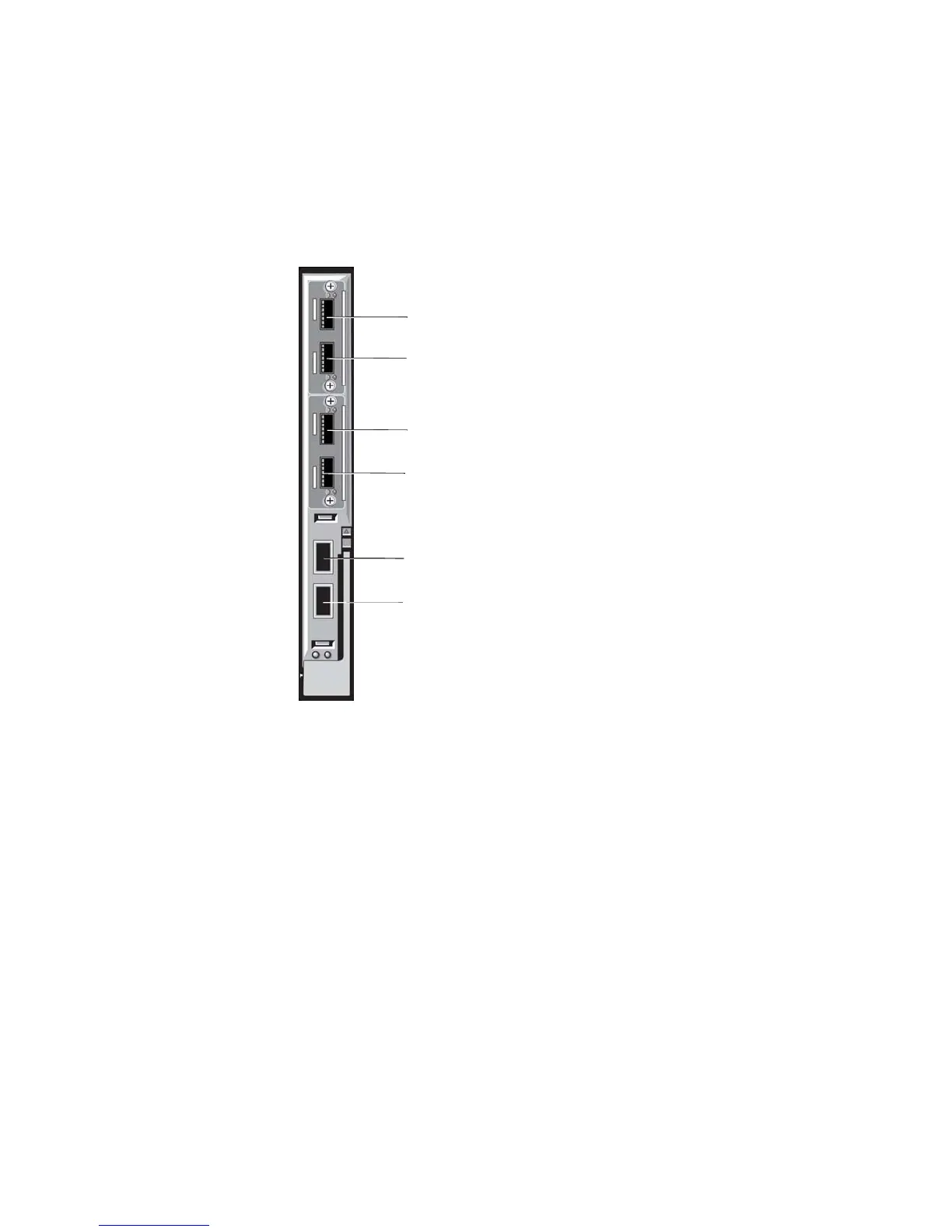
Figure 31-5. Stack Groups on an MXL 10/40GbE Switch
Configuring a Switch Stack
To configure and bring up a switch stack, follow these steps:
1. Connect the switches to be stacked with 40G direct attach or QSFP fibre cables.
2. Configure the stacking ports on each switch.
3. All switches must be booted together.
4. (Optional) Configure management priorities, unit numbers, or logical provisioning for stack units.
Stack Group 0 / Port 33
Stack Group 1 / Port 37
Stack Group 3 / Port 45
Stack Group 2 / Port 41
Stack Group 5 / Port 53
Stack Group 4 / Port 49

Table of Contents

Other manuals for Dell Force10 MXL Blade

Questions and Answers:

Question and Answer IconNeed help?

Do you have a question about the Dell Force10 MXL Blade and is the answer not in the manual?

Dell Force10 MXL Blade Specifications

General IconGeneral
Switching Capacity1.28 Tbps
Forwarding Rate952 Mpps
Product TypeBlade Switch
Latency< 3 microseconds
Operating Temperature0°C to 40°C (32°F to 104°F)
RedundancyYes
ManagementCLI, SNMP, Web
Layer SupportLayer 2, Layer 3
Jumbo Frame SupportUp to 9216 bytes
Management Ports1 x 10/100/1000 Mbps
Storage Temperature-40°C to 70°C
Weight4.5 kg (9.9 lbs)

Related product manuals