Getting Started | 39
For the console port piMnout, refer to Table 3-1.
To access the console port, follow these steps.
External Serial Port with a USB Connector
Table 3-1 lists the pin assignments.
Boot Process
After you follow the Installation Procedure in the Getting Started Guide, the MXL Switch boots up. The
MXL Switch with FTOS version 8.3.16.1 requires boot flash version 4.0.1.0 and boot selector version
4.0.0.0. Figure 3-2 and Figure 3-3 show the completed boot process.
Step Task
1 Connect the USB connector to the front panel. Use the RS-232 Serial Line cable to connect the MXL 10/40GbE
Switch IO Module console port to a terminal server.
2 Connect the other end of the cable to the DTE terminal server.
3
Terminal settings on the console port cannot be changed in the software and are set as follows:
• 9600 baud rate
• No parity
• 8 data bits
• 1 stop bit
• No flow control
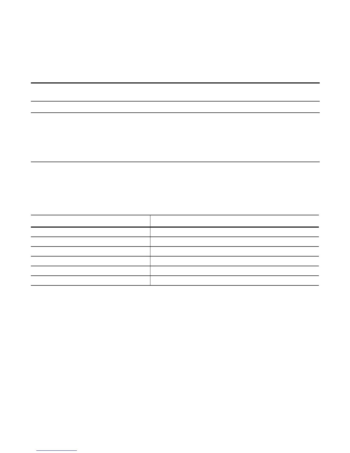
Table 3-1. Pin Assignments
USB Pin Number Signal Name
Pin 1 RTS
Pin 2 RX
Pin 3 TX
Pin 4 CTS
Pin 5, 6 GND
RxD Chassis GND

 Loading...


