31
Power connector: the ‘Abacus 5’ power connector should be connected to a grounded power outlet that meets
the requirements listed in section 2.5.
Main power switch: this is a small switch located next to the power connector. This switch turns off all electrical
power to the ‘Abacus 5’ analyzer. Leaving this switch on allows the ‘Abacus 5’ to remain in the standby state. The
switch is on when it is in the ‘up’ position labeled ‘1’ and is off when it is in the down position labeled ‘0’.
Standby switch: flipping this switch to the ‘up’ position takes the ‘Abacus 5’ main computer out of the standby
state and powers up internal analyzer components. Please note that this switch springs back to the down position
when released and does not stay in the ‘up’ position.
Table 6. Reagent Connector Color Codes
Hardware Key connector: this connection is used to plug in the hardware key supplied with every new package of
genuine Diatron Diatro•Lyse-5p reagent. A new reagent key provides the analyzer with the ability to run 700
measurements. When the measurement count has been exhausted, the ‘Abacus 5’ analyzer stops processing
samples.
Reagent connectors: five color-coded tubing connectors provide connection to the reagents. There are three
reagent connectors and two waste connectors.
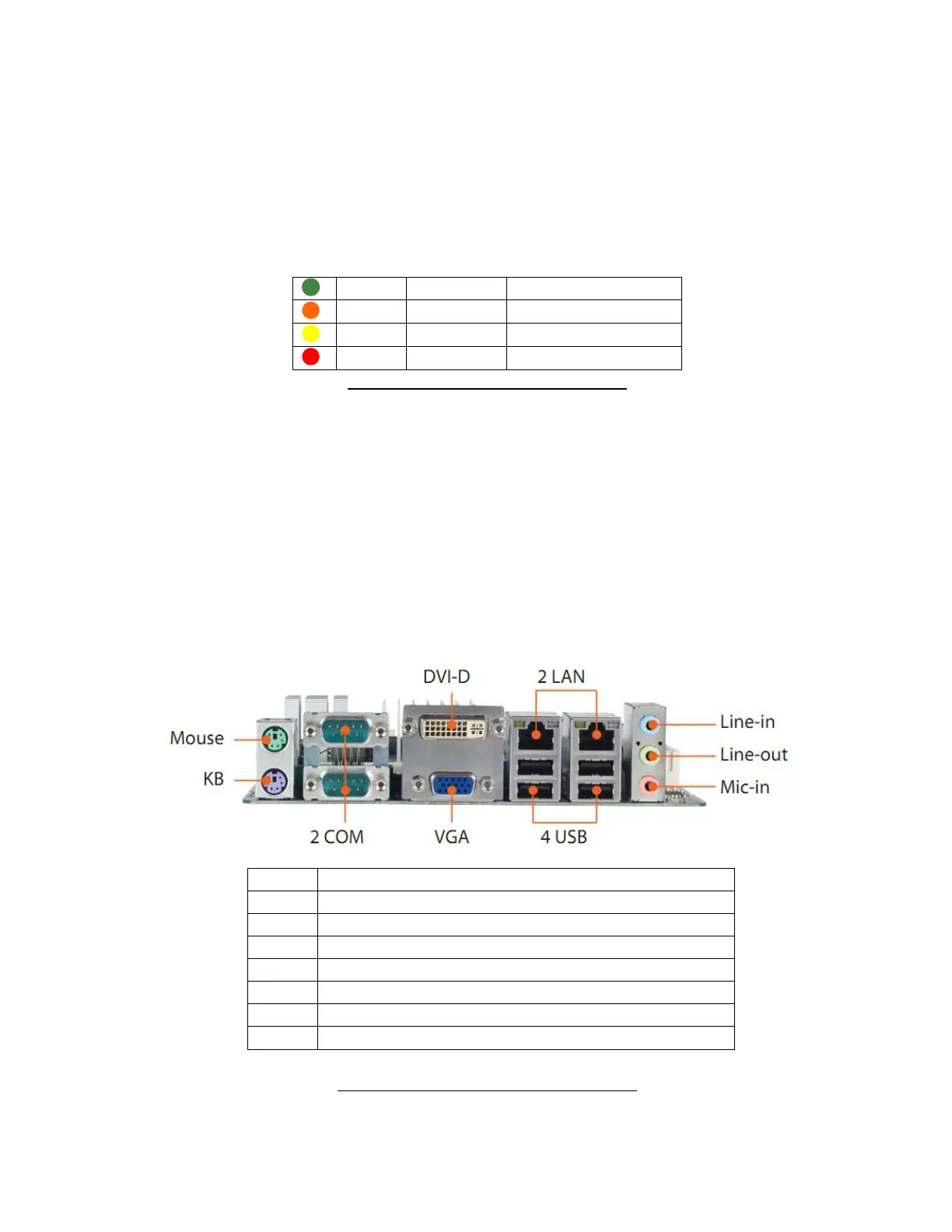
Main board back panel I/O Ports: these are the back panel computers of the ‘Abacus 5’ analyzer main computer
board. They provide standard connection to peripherals such as external keyboard and mouse, printers, bar code
readers.
Figure 11. Main Board Back Panel I/O Ports
PS2 Mouse port for optional mouse
PS2 Keyboard for optional PS2 keyboard
RJ45 Ethernet port for LIS
USB 2.0 ports for peripherals