A-4
Appendix A
A.2 Connection and Setup ...........................................................
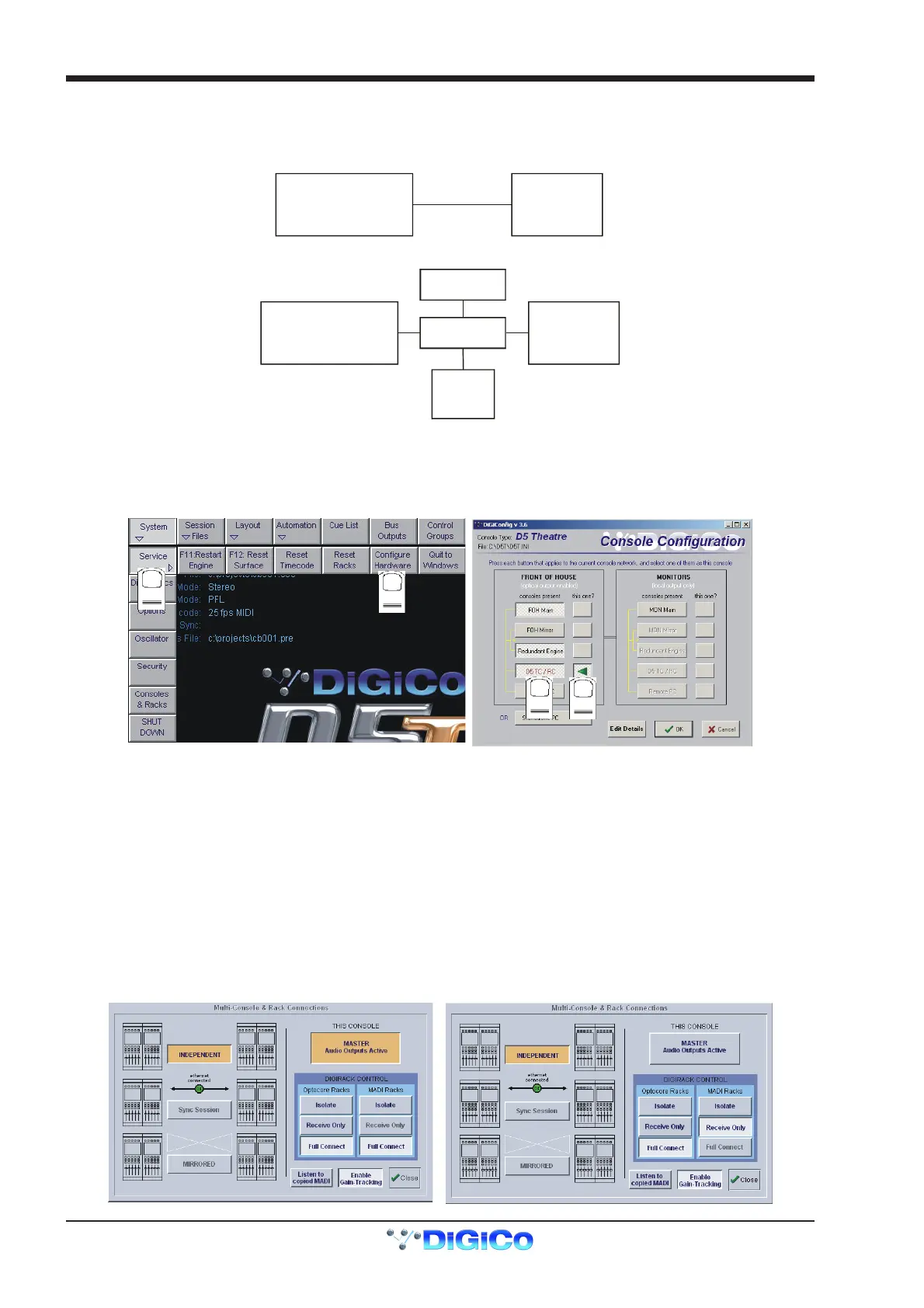
The D5TC is connected to the D5T using a CAT5 Ethernet cable. If these are the only two devices in the system an Ethernet crossed
cable can be directly connected to both but if there is another remote controller, a remote PC running the D5T Cue Editor or a D5T
Redundant Engine in the system then all of these devices should be connected via an Ethernet switch using standard CAT5 cables.
D5-T
OR
D5-T
D5-T RE
CUE
EDITOR
ETHERNET
SWITCH
D5-TC
D5-TC
Crossed
Ethernet Cable
When the TC has been connected and switched on:
1) Press the System/Service/Configure Hardware button to open the DiGiConfig program.
2) Select all the devices in your system by pressing the relevant buttons and then press the This One button for the TC.
3) This will automatically configure the TC but you can press the Edit Details button to view more information.
4) Then press OK to return to the TC software application.
1
2
3
4
A.3 Consoles and Racks Panel ....................................................
If the system has been defined as consisting of more than one device, the Consoles & Racks panel will automatically open on boot up or
load session.
This panel can also be opened from the System menu.
If the crossed Ethernet cable or Ethernet switch has been connected, then the Ethernet Connected line should show a green OK light
and not a red cross.
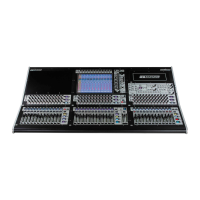
The initial state will have no connection between the devices (Independent) or the racks (Isolated) and the panel appears in order to
prompt the operator to make the necessary connections.
In this state, any gain adjustments made on the console will have no effect as the racks will not be receiving any data.
The console’s MASTER Audio Outputs Active button will normally be highlighted in orange to show that it is the master responsible for
audio processing at this time.
The same button on the TC should not be highlighted at all.
The MADI Rack’s connect states Receive Only and Full Connect are enabled/disabled and set according to the Audio Master active state
– an inactive engine cannot output to a MADI rack.
Main Console Redundant Engine, Mirror Console or Remote