3-6
Chapter 3
3.2.3 Level Trim .............................................................................
This trims the level for each buss signal. For Stereo or Surround busses, you can trim the level of each signal independently using the
fader below the display. The faders can also be assigned to the Limiter controls (see below) - touch the Level Trim display to assign the
fader to the Level control.
3.2.4 Limiter ...................................................................................
The Limiter is a feed-forward system which provides absolute signal limiting. You can operate the on-screen In/Out switch by touching it
or by using the LCD button.
As with the Level, the Limiter Threshold and Release time are set using the fader below the display. To adjust eg the Threshold setting,
touch the on-screen display of the Threshold - this will make the on-screen Threshold slider control turn red, indicating that this control is
now assigned to the physical fader below the screen.
The Over indicator lights up whenever the Limiter is activated, or if the Limiter is switched out, whenever the buss signal level goes over
0dB. Once lit, the Over light stays on until it is touched.
3.2.5 Mute .......................................................................................
Touching the Mute button on the screen or the worksurface cuts the output signal from the relevant buss.
3.2.6 Meters ....................................................................................
The Meters display the signal level, and indicate a peak level.
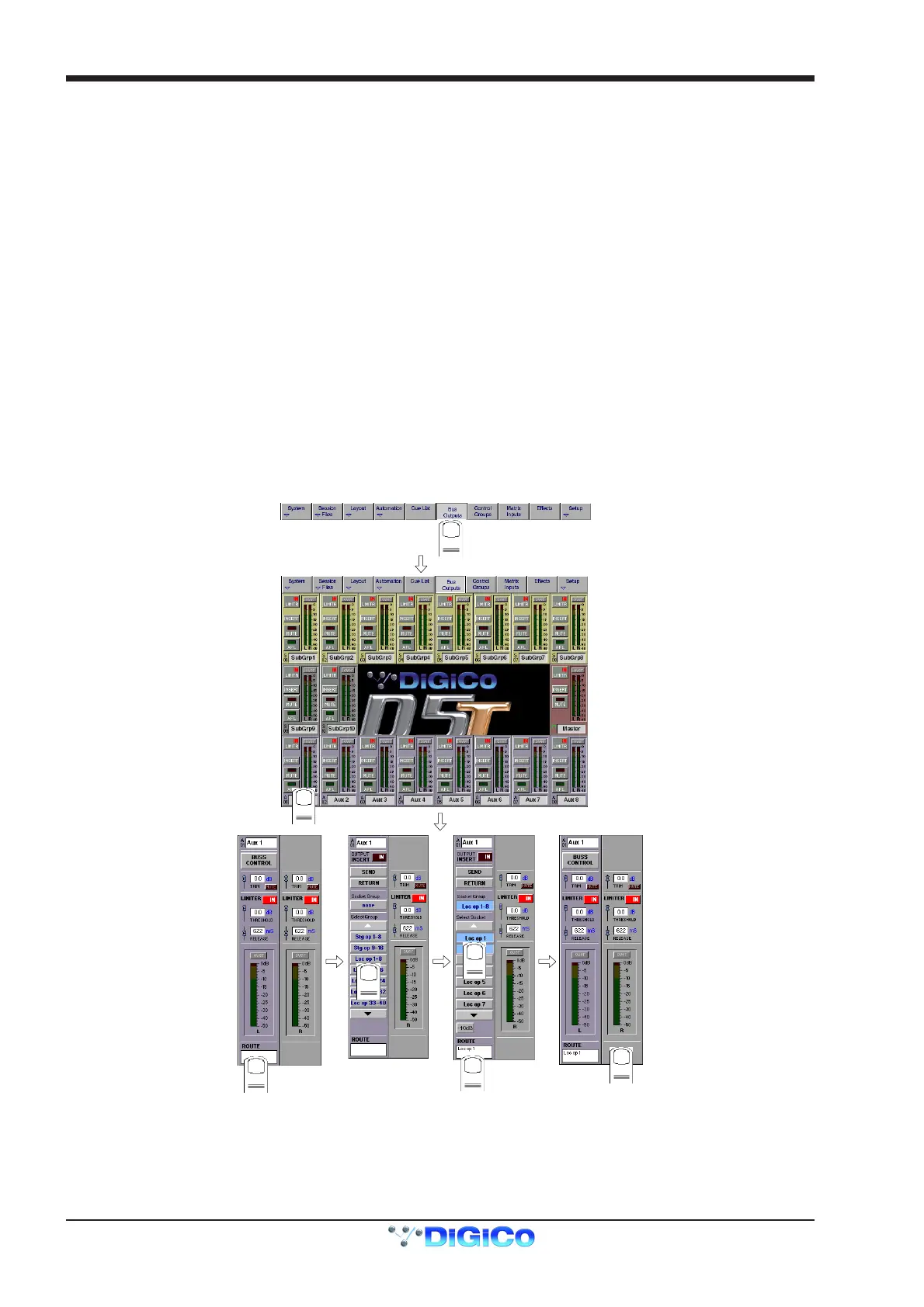
3.2.7 Output Channel Routing .....................................................
The Buss Routing section indicates which output sockets the channel is currently connected to. To alter this routing, touch the Routing
section: you can then select a socket (or a number of sockets) to which the buss signal(s) are routed.
NOTE: If an output socket button is disabled (Text in white) and is touched, a message temporarily pops up explaining why.
1
2
3
4
5
6
7
Note that with Stereo or Surround busses, you cannot route the buss signals separately - by assigning the socket for the left most buss
channel, you also assign the next socket(s) in the socket Group to the remaining buss signal(s). The illustration above shows a stereo
group, so choosing socket Loc op 1 would assign the left buss signal to socket Loc op 1, and the right buss signal to socket Loc op 2.
NOTE: The order of signals output from a surround stem can be adjusted by using the System/Service/Configure Hardware menu.
This closes the current session and opens the DiGiConfig program - For more information, please refer to the Interconnection and
System Setup section.