Chapter 2
2-20
2.3 Ganging
Ganging is the linking of input channel controls which will allow most types of adjustment made to one channel within the gang to be
automatically made to all of the other members.
For example, if 2 channels are ganged and a fader movement is made on one of them, the other will be adjusted in the same way. Ganging
can apply to any number of channels within one Input Bank.
2.3.1 Creating a Gang ...................................................................
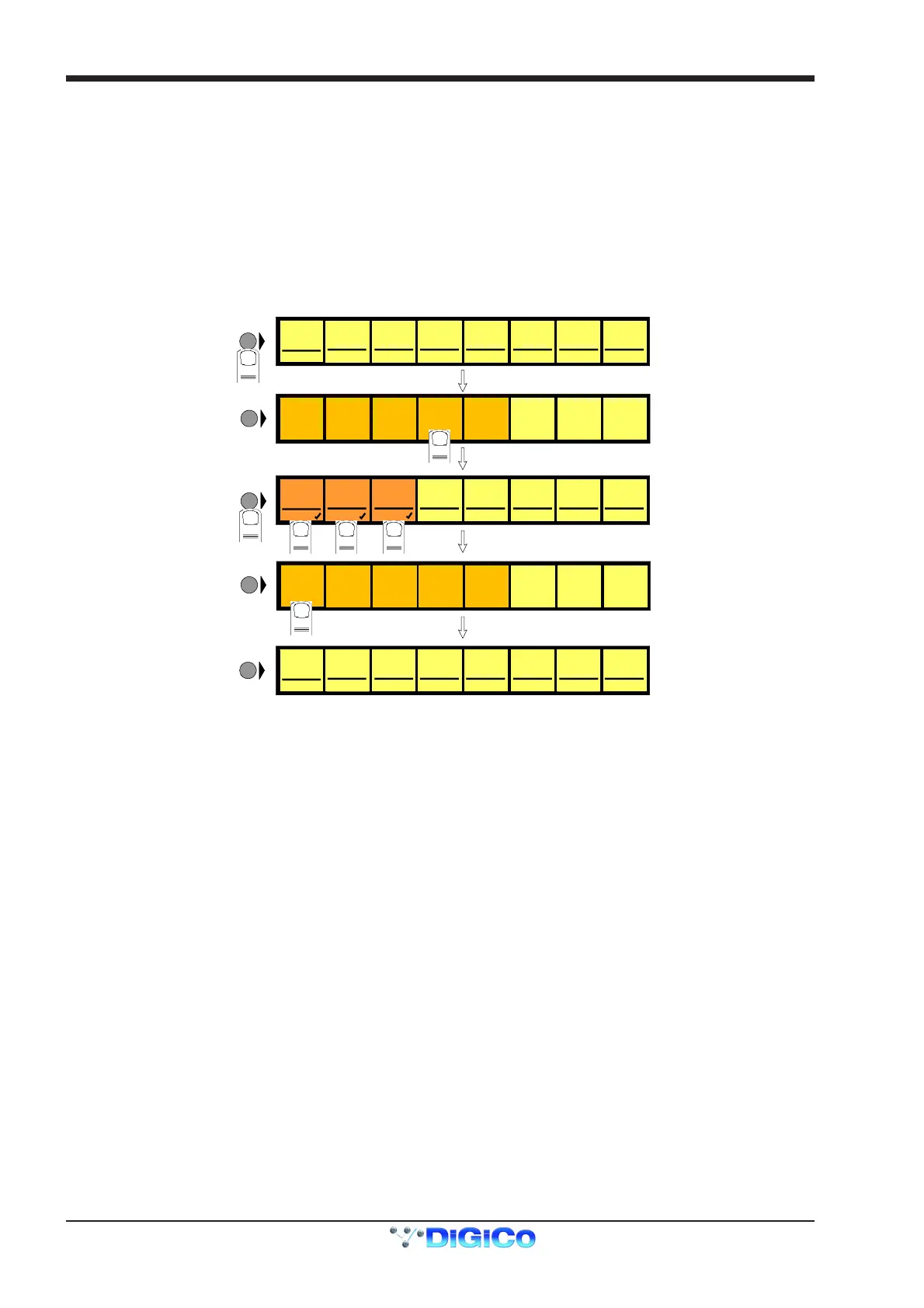
1) Press the Channel LCD Function button on the left of the Input Bank.
2) Press the Build Gangs button.
3) Press the LCD Buttons for the channels that you wish to gang (They will change colour).
4) Press the Channel LCD Function button again to exit ganging mode.
5) Press the Solo button to return to the standard view.
MIC 1
01 Mo
LCD
FUNCTION
MIC 2
02 Mo
MIC 3
03 Mo
MIC 4
04 Mo
MIC 5
05 Mo
MIC 6
06 Mo
MIC 7
07 Mo
MIC 8
08 Mo
LCD
FUNCTION
1
SOLO SOLO SOLO SOLO SOLO S OLO SOLO SOLO
MIC 1
01 Mo
MIC 2
02 Mo
MIC 3
03 Mo
MIC 4
04 Mo
MIC 5
05 Mo
MIC 6
06 Mo
MIC 7
07 Mo
MIC 8
08 Mo
GANG GANG GANG GANG GANG GA N G GA NG GANG
LCD
FUNCTION
3 4 5
6
LCD
FUNCTION
MIC 1
01 Mo
LCD
FUNCTION
MIC 2
02 Mo
MIC 3
03 Mo
MIC 4
04 Mo
MIC 5
05 Mo
MIC 6
06 Mo
MIC 7
07 Mo
MIC 8
08 Mo
SOLO SOLO SOLO SOLO SOLO S OLO SOLO SOLO
SOLO SAFE
AUX SEND
>FADERS
BUILD
GANGS
FADER
ASSIGNS
CHANNEL
SOLO
ASSIGNS
CHANNEL
ONLY
DISPLAY
NAME
SOLO
1OR2
2
SOLO SAFE
AUX SEND
>FADERS
BUILD
GANGS
FADER
ASSIGNS
CHANNEL
SOLO
ASSIGNS
CHANNEL
ONLY
DISPLAY
NAME
SOLO
1OR2
7
To create another new gang you should repeat the process.
When a channel is a member of a gang, a coloured line will appear at the bottom of that channel's screen display. Adjacent gangs are
assigned different colours. Ganging is also indicated by triangular symbols on the LCD buttons.
NOTE: Members of the gang do not have to be in adjacent channels, they can be anywhere within the 8 channels in an input bank.
2.3.2 Clearing or Editing a Gang .................................................
A gang can be cleared or edited at any time by entering the Build Gangs mode as described in section 2.3.1.
To remove a member of the gang press the relevant highlighted LCD Buttons and they will return to their original colour and no longer be
members of the gang.
To clear the gang remove all the members in the same way.
2.3.3 How a Gang Works ..............................................................
When channels are added to a gang their present settings are retained until an adjustment is made to any of the members controls. When
this happens all members of the gang will be adjusted in the same way as the first but relative to their own starting position.
For example, if the channel fader of one member of a gang is at minus 6dB and another is at 0dB, when the first fader is raised to 0dB, the
second will be automatically raised to plus 6dB.
ie. Both faders will be raised by 6dB from their previous position.
A similar situation exists with the other channel controls such as EQ and Auxiliary sends but when any of the gang members' controls
reaches its maximum or minimum level the relative offset relationship is lost.
Only the channel faders can retain their relative offsets after they have reached a maximum or minimum level.
Adjusting settings for one member of a gang
If you wish to adjust the settings for one member of a gang without affecting the others, a member of a gang can be temporarily isolated
from the rest of its gang by holding the channel's solo button down while adjustments are being made. When solo is released the channel
will continue to behave as a normal gang member.
Which controls are affected by ganging?
Screen display changes such as showing the input or group routing modules can be different between gang members but the functions
themselves are always linked.
For example, if 4 channels were members of a gang and a different input source was selected for one of them, the other three input
sources would automatically be assigned to the next consecutive sockets in that input group. This assumes that there are enough input
sources for all the gang members in the socket group. If there are not enough sources, the gang will be allocated as many as are available
at that time.