Chapter 2
2-10
2.2.3 Dynamics Module.................................................................
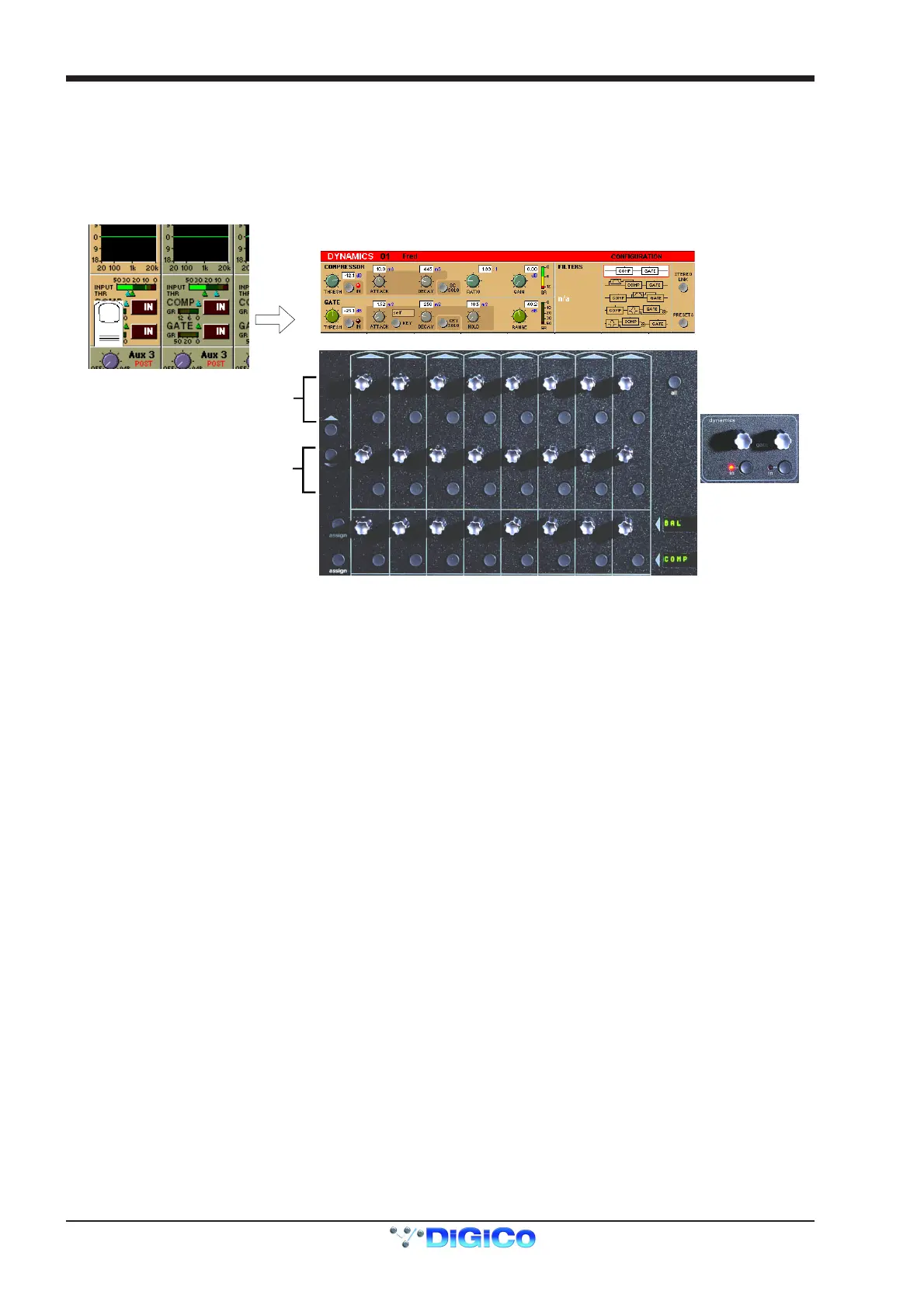
The Dynamics Module on each channel incorporates a Compressor and Gate, and also includes optional Filters for the sidechain and key
signals.
You can display the Dynamics Module by touching the dynamics display on the channel strip. Touching the In / Out buttons will switch the
section On or Off.
When expanded, the Dynamics Module appears across the bottom of the screen, and its settings are changed using the corresponding
controls below the display.
Gate Controls
Compressor Controls
Compressor
The Threshold is the level at which the compression begins to affect the signal. For example, if you set the Threshold to -12dB, this
means that the compressor has no effect until the signal level exceeds -12dB.
The Attack time is the time taken for the attenuation to reach the desired level after an increase in the level of the input signal.
The Decay time is the time taken for the attenuation to reach the desired level after a decrease in the level of the input signal.
The Ratio control lets you set the ratio between the signal level change and the resulting attenuation change. For example, if you set the
Ratio to 2:1, and the signal is above Threshold, a 6dB increase in level will result in a 3db increase in attenuation, so the net effect on the
audio signal will be a level increase of 3dB.
The Gain control allows you to boost the overall level of the audio signal coming out of the compressor, to make up any level lost through
compression.
The Meter provides a constant indication of the compressor gain reduction.
The Sidechain Solo places the Sidechain signal on the Solo buss in PFL (Mono) mode. This is achieved by holding down the corre-
sponding button in the compressor controls below the screen.
Gate
The Threshold is the signal level above which the Gate has no effect.
The Attack time is the time the Gate takes to open once the signal level has risen above threshold.
The Decay time sets the time the Gate takes to close, once the signal level has dropped below the threshold (and the Hold time has
passed - see next paragraph). A long decay time means that the attenuation increases gradually, making any sub-threshold signal fade
out. A short decay time means that the Gate shuts quickly, cutting off the signal abruptly.
The Hold time is an extra period for which the Gate remains open after the signal level has dropped below threshold.
The Range control sets the maximum amount of signal attenuation implemented by the Gate when it is closed (ie when the signal level is
below threshold). A Range setting of 0dB means that the Gate has no effect, while a Range setting of 30dB means that all signal levels
below threshold will be attenuated by -30dB.
The Meter provides a constant indication of the Gate attenuation. If the Gate is fully open, the meter shows full deflection, indicating 0dB
attenuation. If the Gate is fully closed and the Decay and Hold times have passed, the meter shows the amount of attenuation set by the
Range control.
The Gate Key button allows you to select the signal used to trigger the Gate. The default setting is Self, where the level of the channel's
own signal is used as the trigger, but you can use this switch choose a different channel or buss.
Pressing the Gate Key button in the Dynamics panel displays a routing panel from which to select a key source. All input signals and buss
results are listed as well as input channel post-processed signals.
Note: The Signal Group labelled Channels contains the post-processed signals.
Gate Key signals use the channel send resource just like direct output and insert sends. This resource is limited to 96 channels and when
all 96 are used up, other channels listed will be greyed out. The state of channel send resources is displayed on the diagnostics panel.
Note: When the Filters are switched into the Dynamics section the Gate Key Source is automatically switched to its "Self"
setting and disabled.