A
B
C
D
E
F
G
H
L
M
N
P
Ruote - Sospensioni - Freni
Wheels - Suspension - Brakes
sezione / section
G 2
16 SuperSport 800 - M.Y. 2006 - edizione/edition 00
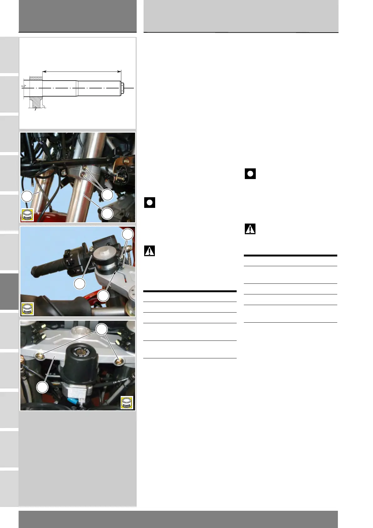
Rimontaggio forcella
anteriore
Procedere al rimontaggio degli steli
posizionandoli, rispetto alla base di
sterzo, all’altezza indicata in figura.
Posizionare gli steli (5) e (6) forcella.
Bloccare alla coppia di serraggio
prescritta (Sez. C 3) le viti (2) e (1) di
fissaggio degli steli alla base (4) e alla
testa di sterzo (3) con la sequenza 1-
2-1.
Quando si rimontano i semimanubri
sulla sommità degli steli è necessario
orientarli rispetto alla testa di sterzo
facendo corrispondere la tacca in
rilievo (A) del semimanubrio con la
fessura della testa sterzo.
Bloccare le viti (23) alla coppia di
serraggio prescritta (Sez. C 3).
Importante
Se durante lo smontaggio sono
state rimosse dalla loro sede,
applicare grasso prescritto sul filetto
delle viti (1), (2) e (23) prima di
procedere al relativo bloccaggio.
Attenzione
Non utilizzare il motociclo senza
il parafango anteriore per evitare che
le tubazioni freno vadano ad
interferire con la ruota durante la
frenata.
Operazioni Rif. Sez.
Installazione cupolino E 1
Installazione carene E 2
Installazione ruota
anteriore
G 1
Installazione parafango
anteriore
E 3
Installazione pinze
freno anteriori
G 3
Refitting the front fork
Refit the fork legs. Fork leg height
above bottom yoke top face is
reported in the figure.
Position the fork legs (5) and (6)
correctly. Tighten screws (2) and (1)
to the specified torque (Sect. C 3) in a
1-2-1 sequence to clamp the fork legs
to the bottom yoke (4) and steering
head (3).
When refitting the handlebars on the
fork legs, ensure that handlebar notch
(A) matches the slot on steering head.
Tighten the screws (23) to the
specified torque (Sect. C 3).
Caution
If they have been removed
from their seats during the
disassembly procedure, grease the
threads of the screws (1), (2) and (23)
with the specified grease before
tightening.
Warning
Do not ride without the front
mudguard, or the brake hoses might
contact the wheel under braking.
Operations See Sect.
Install the headlight
fairing
E 1
Install the fairings E 2
Install the front wheel G 1
Install the front
mudguard
E 3
Install the front brake
calipers
G 3
256 mm
+0,1
B
2
5
6
23
24
B
A
1
3
B