A
B
C
D
E
F
G
H
L
M
N
P
Ruote - Sospensioni - Freni
Wheels - Suspension - Brakes
sezione / section
G 6
33 SuperSport 800 - M.Y. 2006 - edizione/edition 00
Rimontaggio impianto
freno posteriore
Attenzione
Una tubazione mal posizionata
può causare un malfunzionamento
dell’impianto frenante e può
ostacolare le parti in movimento del
motociclo.
Se è stato rimosso il sensore velocità
(13), posizionarlo sulla piastra porta
pinza con il distanziale (8) e serrare la
vite (14) alla coppia prescritta (Sez. C
3).
Note
Il traferro del sensore (13) e vite
di fissaggio disco freno deve essere
compreso tra 0,6÷2,2 mm.
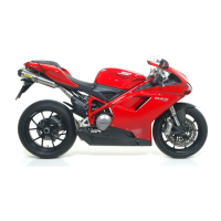
Il fissaggio del tubo freno sulla pinza
deve essere eseguito interponendo
sul raccordo le apposite guarnizioni in
rame (2).
Orientare i racconti del tubo (A) come
indicato in figura.
Serrare le viti speciali (1) alla coppia
prescritta (Sez C 3).
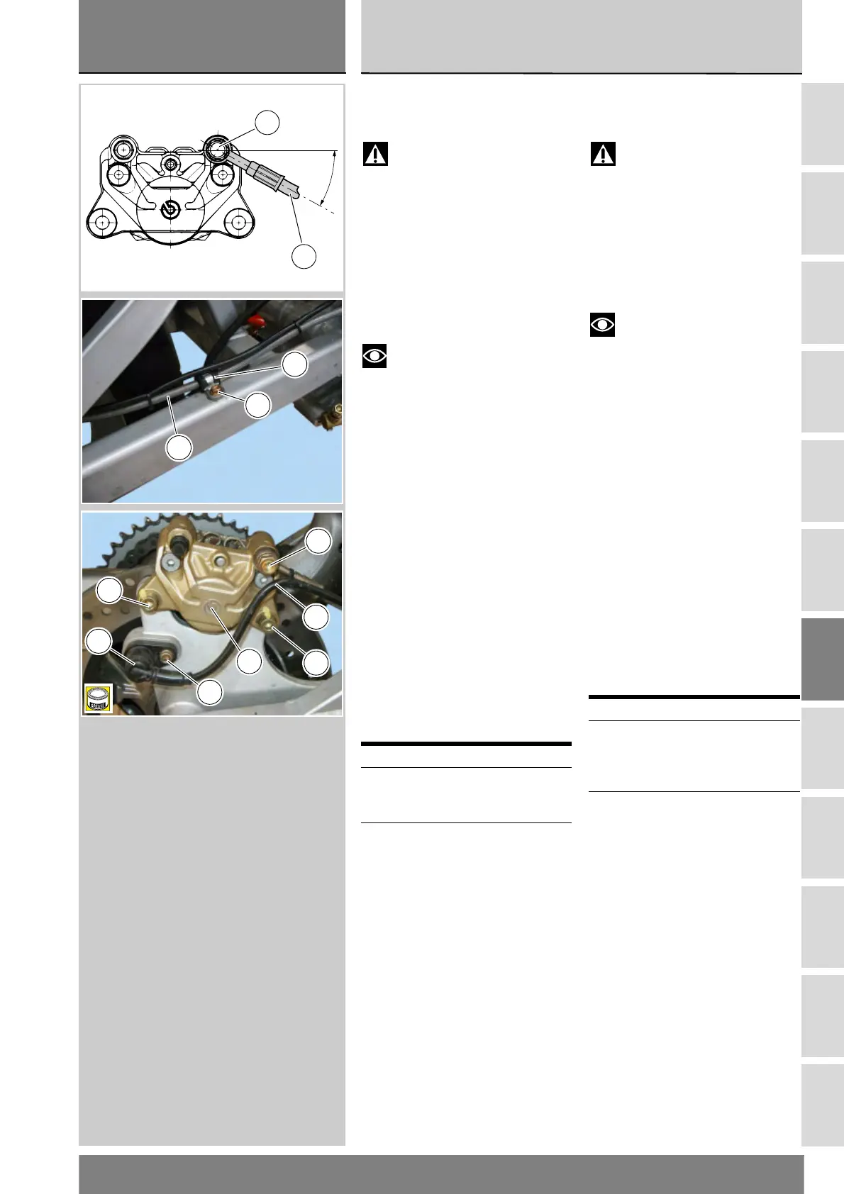
Posizionare il tubo freno (A) sul
forcellone e fissare la graffetta (12)
con la vite (7).
Inserire la pinza freno posteriore (3)
sul disco freno e allinearla ai fori della
piastra portapinza.
Applicare grasso su filetto e
sottotesta delle viti (5).
Serrare le viti (5) alla coppia prescritta
(Sez. C 3).
Operazioni Rif. Sez.
Serrare vite fissaggio
tubazione alla pompa
freno posteriore
F 4
Riempire il circuito
impianto frenante
D 4
Refitting the rear brake
system
Warning
Incorrectly positioned hoses
can cause brake faults and interfere
with moving parts.
If the speed sensor (13) has been
removed, position it to the caliper
mounting plate with the spacer (8)
and tighten the screw (14) to the
specified torque (Sect. C 3).
Note
The air gap of sensor (13) and
brake disc retaining screw must be
between 0.6 and 2.2 mm.
Make sure to fit the special copper
gaskets (2) to the connector when
connecting the brake hose to the
brake caliper.
Position hose (A) fittings as shown.
Tighten the special screws (1) to the
specified torque (Sect. C 3).
Position the brake hose (A) to the
swingarm and secure the retainer (12)
with the screw (7).
Fit the rear brake caliper (3) to the
brake disc matching the holes in the
caliper plate.
Grease the thread and underhead of
the screws (5).
Tighten the screws (5) to the
specified torque (Sect. C 3).
Operations See Sect.
Tighten the screw
retaining the hose to
the rear brake master
cylinder
F 4
Fill the braking circuit D 4
30˚±2˚
1
A
7
12
A
5
3
1
5
14
13
A
B
 Loading...