A
B
C
D
E
F
G
H
L
M
N
P
Motore
Engine
sezione / section
N 9.1
129 SuperSport 800 - M.Y. 2006 - edizione/edition 00
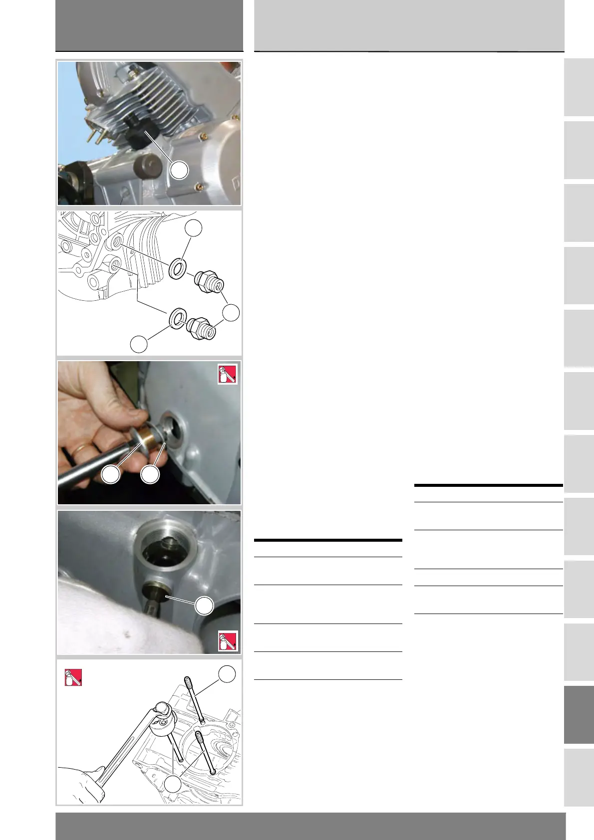
Rimontaggio elementi
esterni
Verificare le condizioni della
guarnizione OR (11) ed
eventualmente sostituirla.
Installare la valvola sfiato vapori olio
(10) nel basamento con guarnizione
OR (11) e bloccarla alla coppia
prescritta (Sez. C 3).
Avvitare i due nippli (14) con le
relative guarnizioni di raccordo
tubazioni olio alla coppia prescritta
(Sez. C 3).
Posizionare la molla by-pass (29) e
avvitare il nipplo (17) di supporto
cartuccia filtro olio alla coppia
prescritta (Sez. C 3).
Avvitare il tappo di scarico (9) con la
relativa guarnizione (8) e serrarlo alla
coppia prescritta (Sez. C 3) applicando
sul filetto bloccante prescritto.
Rimontare l’interruttore folle (19) e la
relativa guarnizione (20) serrandolo
alla coppia prescritta (Sez. C 3).
Applicare frenafiletti sul tappo (27),
impuntarlo con la relativa guarnizione
e serrare il tappo alla coppia prescritta
(Sez. C 3).
Rimontare il filtro a rete (18) con
relativa guarnizione, come descritto
alla Sez. D 4.
Rimontare il saltarello e il puntalino
fissa marce (Sez. N 7.1).
Procedere al montaggio dei prigionieri
(12) sui semicarter, applicando
bloccante sul filetto e serrandoli alla
coppia prescritta (Sez. C 3). Utilizzare
un attrezzo del tipo raffigurato.
Operazioni Rif. Sez.
Rimontare il gruppo
cilindro/pistone
N 5
Rimontare il gruppo
teste completo e gli
organi distribuzione
N 4.2
Rimontare il filtro olio a
cartuccia
D 4
Rimontare l'impianto di
lubrificazione
N 2.1
Installare il motore nel
telaio
N 1
Reassembling the outer
parts
Check O-ring (11) for wear. Change, if
necessary.
Fit oil breather valve (10) with O-ring
(11) inside engine block and tighten to
the specified torque (Sect. C 3).
Tighten the two nipples (14) with oil
tube seals to the specified torque
(Sect. C 3).
Position the by-pass spring (29) and
tighten the nipple (17) supporting the
oil filter cartridge to the specified
torque (Sect. C 3).
Tighten the drain plug (9) with seal (8)
to the specified torque (Sect. C 3)
after applying the recommended
threadlocker.
Refit the neutral light switch (19) with
seal (20) and tighten to the specified
torque (Sect. C 3).
Apply threadlocker to the plug (27), fit
the seal, start it in its thread and
tighten it to the specified torque
(Sect. C 3).
Refit mesh filter (18) with seal, as
described in Sect. D 4.
Refit the ratchet and gear stopper
(Sect. N 7.1).
To refit stud bolts (12) on casing,
apply speed bond on threads and
tighten to the specified torque (Sect.
C 3). Use the suitable tool (shown).
Operations See Sect.
Refit the cylinder /
piston assy
N 5
Refit complete head
assembly and timing
system parts
N 4.2
Refit oil cartridge filter D 4
Refit the lubrication
system
N 2.1
Refit engine to frame N 1
10
8
14
8
9 8
LOCK
9
27
5
LOCK
12
12
2
LOCK