A
B
C
D
E
F
G
H
L
M
N
P
Mototelaio
Frame
sezione / section
H 5
17 SuperSport 800 - M.Y. 2006 - edizione/edition 00
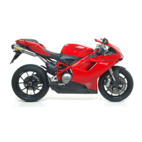
Ricomposizione
cavalletto laterale
Infilare la stampella laterale (1),
opportunamente ingrassata, nella
piastra (3) e fissarla con il perno (8) e
il dado (9).
Serrare il dado (9) alla coppia
prescritta (Sez. C 3).
Posizionare le molle (6) di ritorno
cavalletto, fissandole sul perno
piastra (3) e sulla stampella (1).
Posizionare l’interruttore (5) sulla
piastra, in appoggio sul perno (8).
Montare la vite (4) di fissaggio e
bloccarla alla coppia prescritta (Sez. C
3).
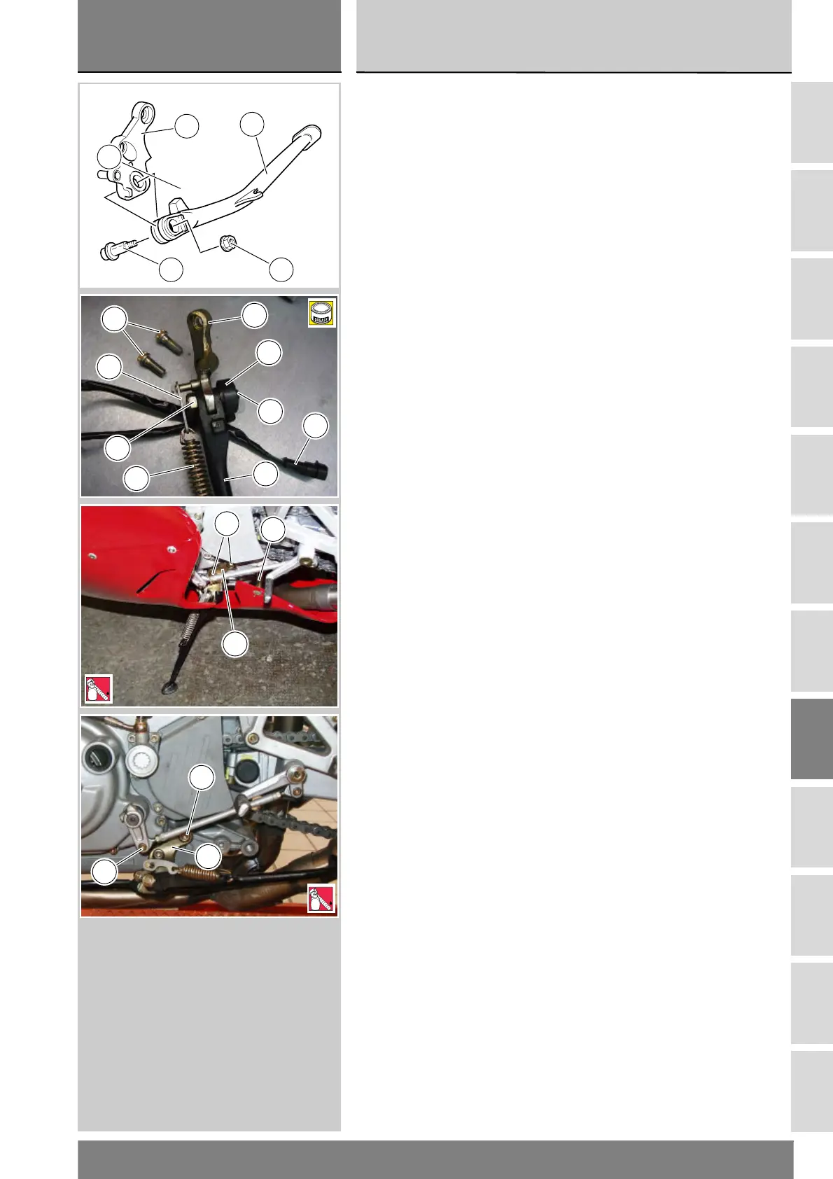
Rimontaggio cavalletto
laterale
Posizionare la piastra (3) sostegno
cavalletto sul telaio e montare le due
viti (2) applicando frenafiletti
prescritto.
Serrare le viti (2) alla coppia prescritta
(Sez. C 3).
Collegare il connettore
dell’interruttore cavalletto laterale al
cablaggio principale del veicolo.
Per il posizionamento del cablaggio
interruttore cavalletto fare riferimento
alle tavole Sez. P 1.
Per le versioni carenate, controllare
che sia posizionata la colonnetta (11)
e rimontare la carena sinistra (Sez. E
2).
Reassembling the side
stand
Grease the stand (1) and fit it to the
plate (3). Secure it with pivot (8) and
nut (9).
Tighten the nut (9) to the specified
torque (Sect. C 3).
Position the stand return springs (6),
fix them to the pivot of plate (3) and to
the stand (1) and tighten.
Position the switch (5) to pivot (8) on
the plate.
Fit the retaining screw (4) and tighten
to the specified torque (Sect. C 3).
Refitting the side stand
Position the side stand plate (3) to the
frame. Apply the specified
threadlocker to the threads of the two
screws (2) and start the screws in
their holes.
Tighten the screws (2) to the
specified torque (Sect. C 3).
Connect the connector of the side
stand switch to the main wiring
harness.
See the tables in Sect. P 1 for side
stand switch cable routing.
In faired versions, ensure that stud
bolt (11) is in place and refit the left
fairing (Sect. E 2).
3
1
9
7
8
6
4
3
2
5
5
9
7
A
1
3
2
11
5
LOCK
2
3
2
5
LOCK