A
B
C
D
E
F
G
H
L
M
N
P
Impianto elettrico
Electric system
sezione / section
P 3
40 SuperSport 800 - M.Y. 2006 - edizione/edition 00
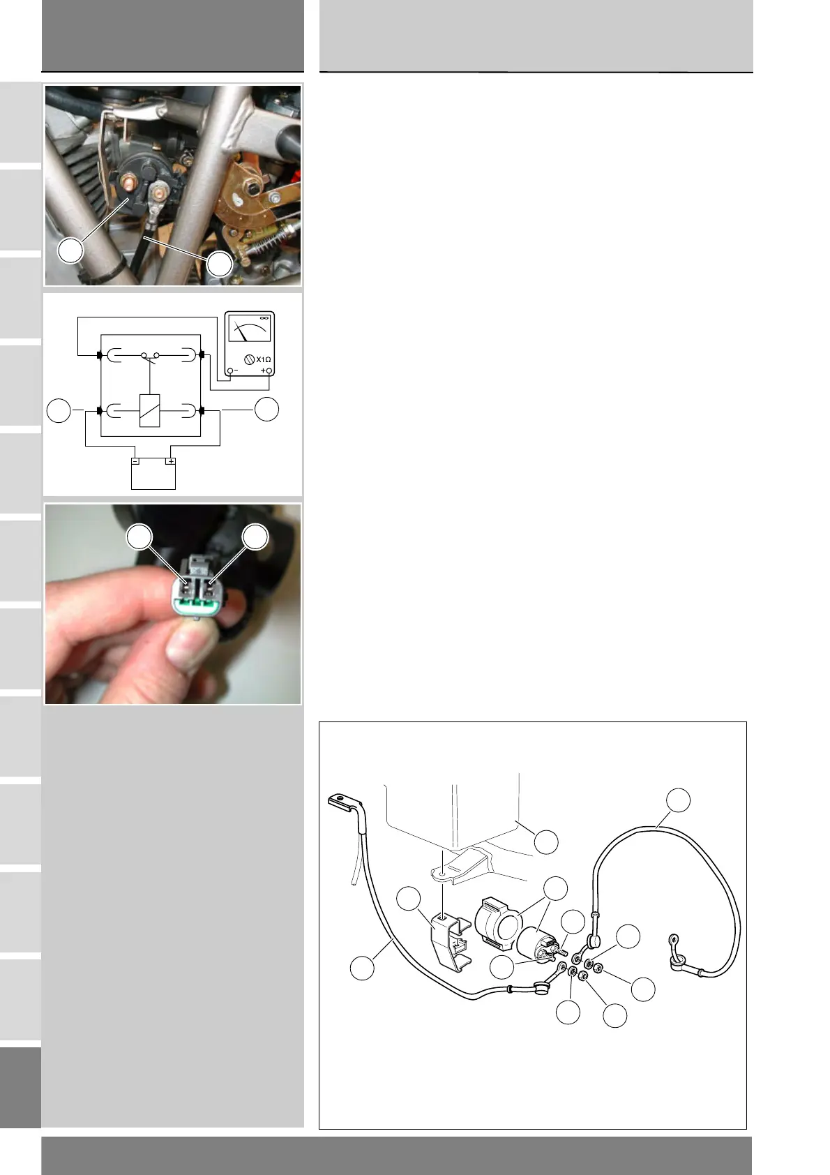
Teleruttore avviamento
Il teleruttore avviamento (1) è fissato
elasticamente al telaio e alla scatola
filtro aria (5) lato destro (Sez. L 7).
Scollegare la batteria (Sez. P 2).
Rimuovere il teleruttore avviamento
dal supporto (6).
Svitare i dadi (4) facendo attenzione
alle rosette elastiche (3).
Rimuovere il cavo (2) teleruttore-
motorino avviamento. Rimuovere il
cavo (5) teleruttore-batteria.
Scollegare il connettore (2) del
teleruttore avviamento dal cablaggio
(fare riferimento alle tavole del
capitolo “Disposizioni dei cablaggi sul
motociclo” sezione P 1).
Controllo funzionalità
teleruttore avviamento
Applicare una tensione di 12V
(batteria) ai due terminali (A) positivo
e (B) negativo del connettore.
Con un multimetro collegato fra i due
poli (perni filettati (C) e (D)) del
teleruttore verificare la presenza della
continuità
elettrica (Sez. P 9). Se non è presente
continuità elettrica, sostituire il
teleruttore.
Durante il rimontaggio, verificare che
i poli (C) e (D) non siano ossidati e
applicare spray idrorepellente.
Serrare i dadi (4) alla coppia prescritta
(Sez. C 3).
Rimontare il connettore (2) al
cablaggio (fare riferimento alle tavole
del capitolo "Disposizioni dei cablaggi
sul motociclo" sezione P 1).
S
3
4
4
3
2
1
5
6
D
C
Starter contactor
The starter contactor (1) is rubber-
mounted to the frame and the air box
(5), right side (Sect. L 7).
Disconnect the battery (Sect. P 2).
Remove the starter contactor from
support (6).
Undo the nuts (4) and collect the
spring washers (3).
Remove the contactor-starter motor
cable (2). Remove the contactor-
battery cable (5).
Disconnect starter contactor
connector (2) from the wiring (see
diagrams in "Arrangement of wiring
on the frame" under Sect. P 1).
Starter contactor operational
check
Apply a 12V (battery) across the
positive (A) and negative (B) terminals
of the connector.
Connect a multimeter between the
two
poles [threaded pins (C) and (D)] of
the starter contactor and then check
for electric continuity
(Sect. P 9). If continuity is not
ensured, replace the starter
contactor.
At reassembly, check that contacts
(C) and (D) are not oxidized and use
waterproof spray.
Tighten the nuts (4) to the specified
torque
(Sect. C 3).
Connect connector (2) to the wiring
(see diagrams in "Arrangement of
wiring on the frame" under Sect. P 1).
1
2
12V
A
B
+ -
 Loading...