99
20-2-4. Sending Tally Signals to Tally Units
The tally assignments to the Tally Units are made in the TALLY COLOR, TALLY1 and TALLY2
submenus in the [SETUP- EXT I/F] menu as shown below.
(1)Set up the tally colors in the [SETUP- EXT I/F-TALLY COLOR] menu. (See section
20-2-1.
"Tally Color Setting".) Tally color settings are common with other tally modules such as
the GPI IN/TALLY OUT connector.
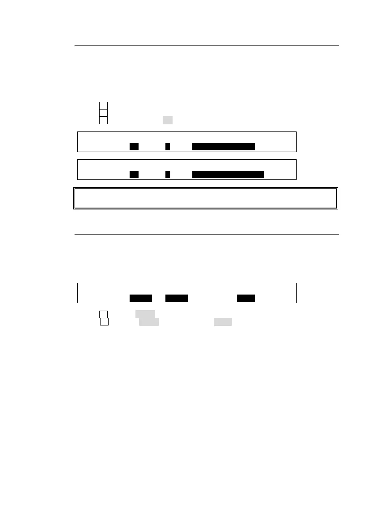
(2)Display the [SETUP-EXT I/F-TALLY1 (or TALLY2)] menu.
(3) Turn F2 to select the pin number at P NO.
(4) Turn F3 to select a tally at FUNCTION. See the table "TALLY function." (p97)
(5) Turn F1 to set ENABLE to ON to enable TALLY Unit 1 (or 2).
EXT I/F :ENABLE :P NO : FUNCTION : 1/1
TALLY1 : =ON : =1 : =TALLY RED IN01
EXT I/F :ENABLE :P NO : FUNCTION : 1/1
TALLY2 : =ON : =1 : =TALLY GREEN IN01
The setting procedure for TALLY2 is the same as for TALLY1. See HVS-TALOC/TALR
operation manual for details about tally connection and operation.
20-2-5. Connection Settings with Tally Units (RS-422 port setting)
Up to two tally units are connected in series to the switcher via RS-422 connector. The
connection settings with Tally Units are made in the [SETUP - EXT-IF-RS-422] menu as
shown below.
(1) Open the [SETUP-EXT I/F-RS-422] menu.
EXT I/F :SELECT :FUNC :BAUDRAT:PARITY : 1/1
RS-422 : =RS422: =TALLY: =38400: =EVEN :
(2) Turn F1 to select RS422.
(3) Turn F2 to select TALLY. Set the parity to EVEN. The baud rate is automatically set
according to the tally unit.
(4) Restart HVS-300HS/RPS. (See section
19-1. "Rebooting System".)



 To Next Page