2
2. Panel Descriptions
2-1. HVS-300HS (Standard Model)
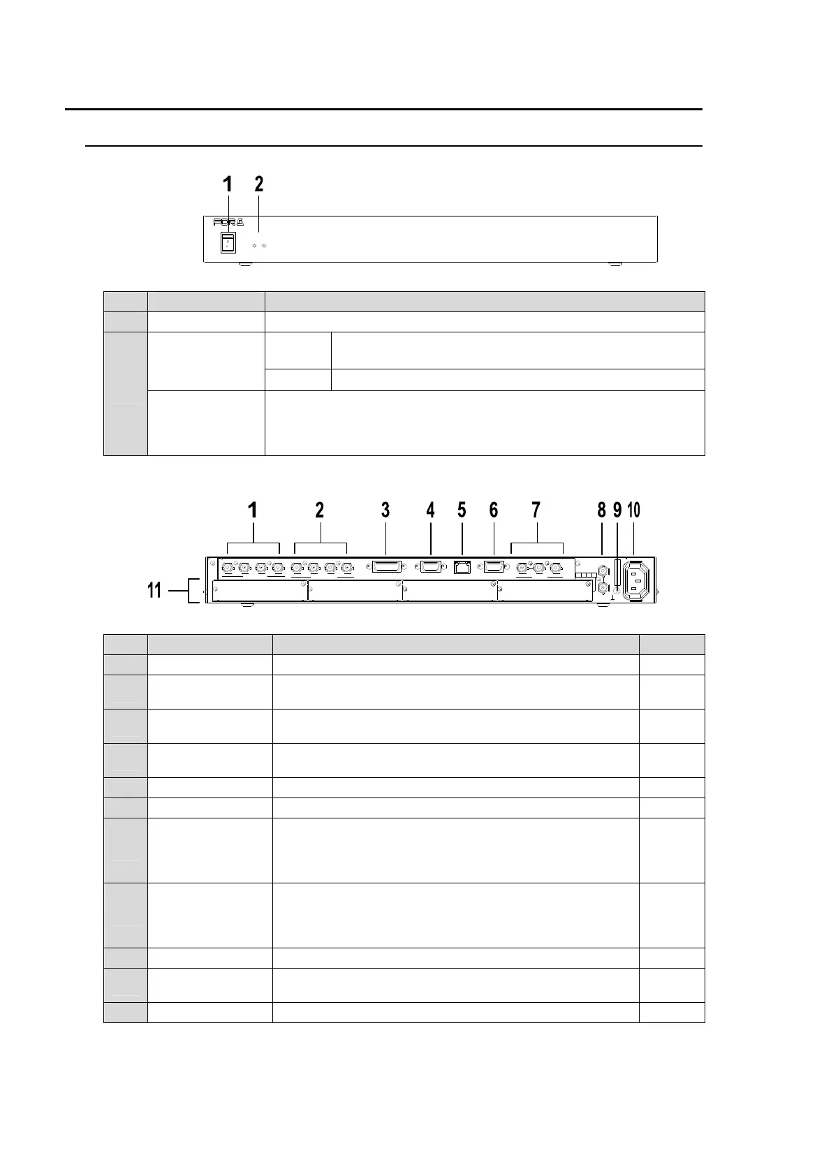
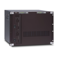
Front Panel
No. Name Description
1 Power switch For power ON/OFF.
2
POWER
indicator
Lit
green
Power is supplied to the unit.
Unlit Power is supplied to the unit.
ALARM
indicator
Lit red when a cooling fan fails. In such a case, power off the unit and
consult your FOR-A supplier. The indicator is normally unlit.
This indicator works the same as the ALARM indicator located on the
Control panel.
Rear Panel
No. Name Description Refer to
1 SDI INPUT Used to input HD/SD SDI video signal. 4 inputs (BNC) 6
2 SDI OUTPUT
Used to output HD/SD SDI video signal. 4 outputs (2
programs and 2 auxiliary outputs) (BNC)
7
3
GPI IN/
TALLY OUT
Used for GPI input/output and Tally output. (15-pin D-sub,
female)
2-5-3
4 RS-422
Used to connect HVS-30RU and Hanabi tally units.
(9-pin D-sub, female)
2-5-2
5 LAN Used for 10BASE-T Ethernet connection. (RJ-45)
6 EDITOR Used for editor connection. (9-pin D-sub, female) 2-5-1
7 GENLOCK
Used to input/output a genlock signal; tri-level sync or
black burst. (BNC)
The center terminal is used for loopthrough connection. It
must be 75-ohm terminated if not looped-through.
18-2
8 TO OU
Used for HVS-30OU connection via Arcnet. It can be also
used to connect the Hanabi AUX control boxes. (BNC)
One of two terminals is used for loopthrough connection.
It must be 75-ohm terminated if not looped-through.
3-1
9 Ground terminal Used for system grounding.
10 AC IN
Used for AC power connection via supplied cable.
(AC100V-240V 50/60Hz)
11 Option Slots Used to install optional input/output expansion cards. 2-4
HVS-300HS
ALARM
OFF
POWER
ON
POWER
DIGITAL VIDEO SWITCH ER
GPI IN/T ALLY OUT RS-422 EDITOR
REF IN
REF OUT
TO O U
4321
SDI INPUT
AU X 2AUX 1PGM 2PGM 1
SDI OUTPUT
AC 100-2 40V 50/60H z IN
OPTION SLOT
AB DC
S/No.
L
A
N
(
1
0
/1
0
0
B
A
S
E
-
T
)
GENLO CK



 To Next Page