Onboard indicators and controls
VGA
Management
LAN
SSD2
M.2
M.2
SSD1
CPU 2 DIMM 2J
CPU 2 DIMM 1H
CPU 2 DIMM 1G
CPU 2 DIMM 2G
CPU 2 DIMM 1J
CPU 2 DIMM 2H
CPU 2 DIMM 1K
CPU 2 DIMM 2L
CPU 2 DIMM 2M
CPU 2 DIMM 1M
CPU 2 DIMM 2K
CPU 2 DIMM 1L
CPU 1 DIMM 1C
CPU 1 DIMM 2C
CPU 1 DIMM 1B
CPU 1 DIMM 2B
CPU 1 DIMM 1A
CPU 1 DIMM 2A
CPU 1 DIMM 2D
CPU 1 DIMM 1D
CPU 1 DIMM 2E
CPU 1 DIMM 1E
CPU 1 DIMM 2F
CPU 1 DIMM 1F
CPU 1
CPU 2
JP3
JP2
JP1
1
12
PUMP1
PUMP2
FAN 5/6 SYS
VROC
Front
Panel
SATA ODD
Slimline6
C
Q
A
USB3.0
Front
INDICATE CSS
CLR CMOS
TPM
Slot OCP module
Slot 2 (CPU1)
Slot Riser Card Slot 5 (CPU2)
Slot 1 (CPU1)
Slot 8 (CPU2)
Micro SD
ROC
USB5
Battery
FAN 3/4 SYS
FAN 1/2 SYS
FAN 7/8 SYS
FAN 9/10 SYS
FAN 11/12 SYS
OOB
Expander I2C
Expander PWR
HSBP PWR
Front
VGA
Serial
iRMC
S5
PCH
USB 3.0
Slimline5
HDD LED
B
G
F
L
H
H
H
H
M
F
I
N
F
F
Slot OCP module
P30
HSBP PWR
R
R
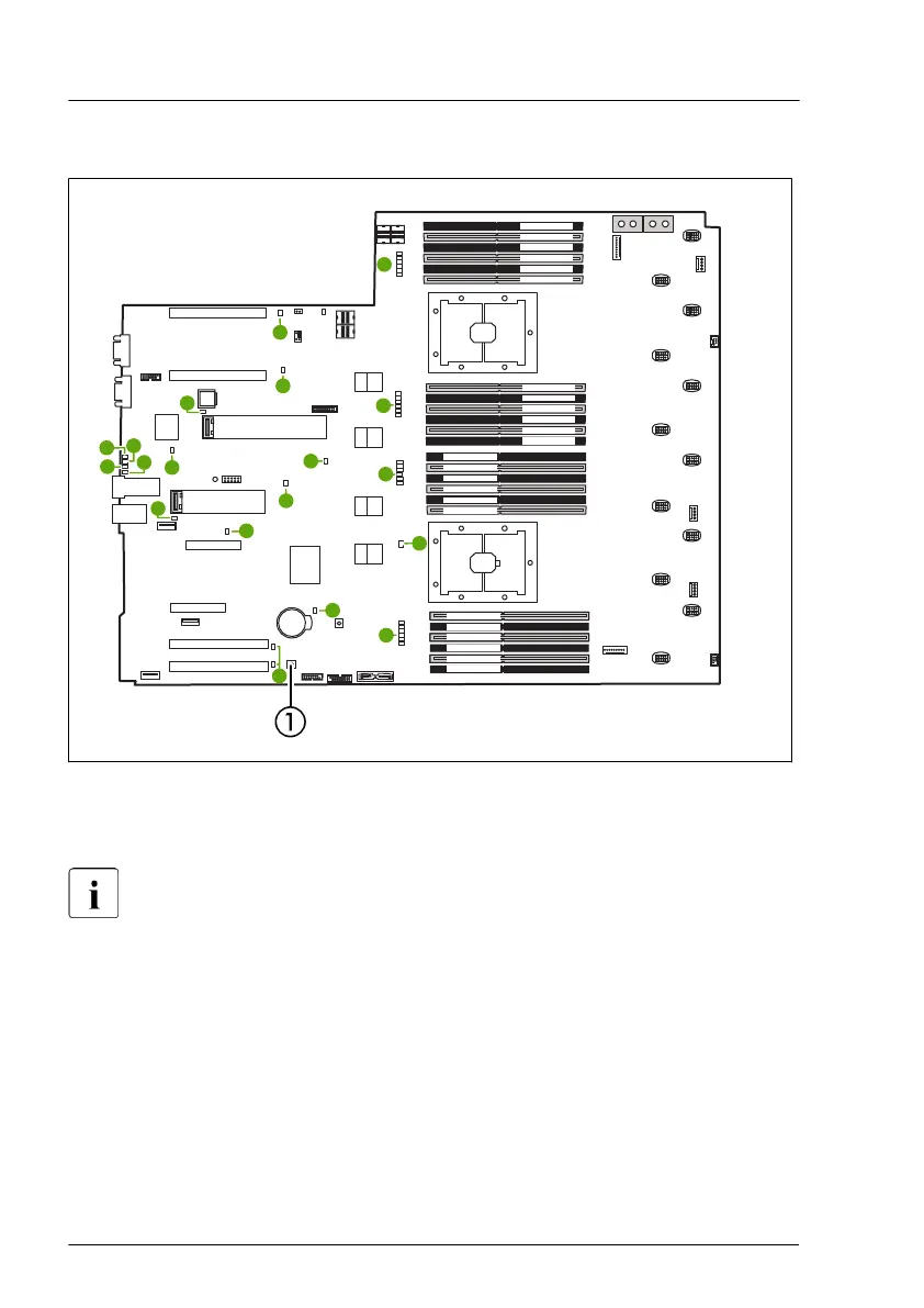
Figure 244: Onboard indicators and Indicate CSS button on the bottom system board
1 Indicate CSS
LEDs A, B, C, and Q are visible from outside on the server rear. All other
LEDs are only visible if the server cover has been opened.
If the server has been powered off (power plugs must be disconnected) it is
possible to indicate the faulty component by pressing the indicate CSS button.
The LEDs have the following meaning:
Appendix A
408 Upgrade and Maintenance Manual RX4770 M5
 Loading...