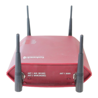
Fig. 14: bintec W2002 underside
bintec W1002, bintec W2002 underside
1 POWER Socket for plug-in power pack
2 CONSOLE Serial Interface
3 RESET Reset button
4 ETH1 / ETH2 10/100 Base-T Ethernet interface
5 bintec W2002:
ANT1 AUX/ANT2
AUX
Connections for screwing on the external antennas
bintec W1002:
ANT1 AUX/ANT2
Main
bintec W2002:
ANT1 Main/ANT2
Main
Top (Fig.)
Connections for screwing on the external antennas
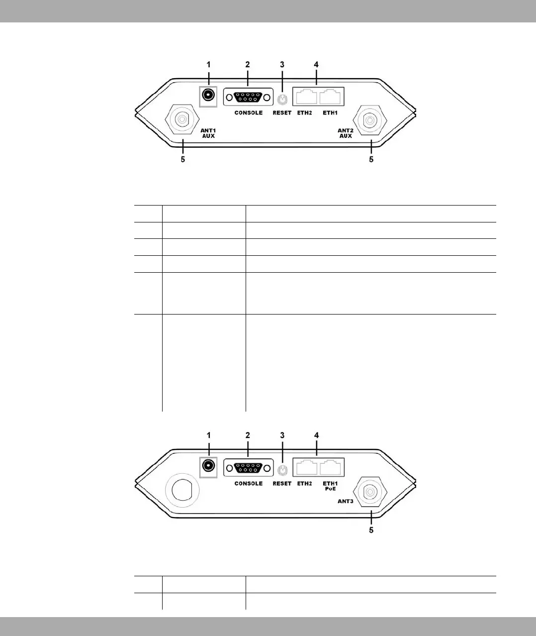
Fig. 15: bintec W1002n underside
bintec W1002n underside
1 POWER Socket for plug-in power pack
2 CONSOLE Serial Interface
Funkwerk Enterprise Communications GmbH
6 Technical data
bintec W1002/W1002n/W2002/WIx040/WIx065 33