LED State Information
(2x green)
on Cable plugged in and link
on (flickering) Cable plugged in and link with data
traffic
SFP (green) off No data traffic
on Data traffic via the SFP interface.
on (flickering)
Cable plugged in and data traffic
During the boot operation, only the red LED is on. The other LEDs then come on during
booting (if the units are initialised).
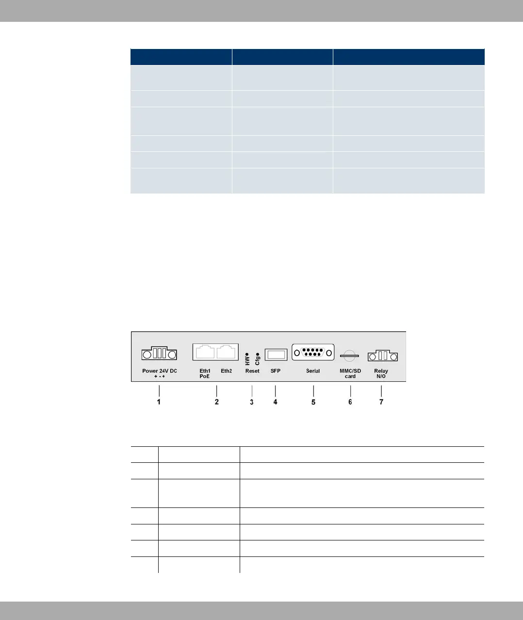
6.2.4 Connections
All connections are located on the underside of the device. bintec WI1040, WI2040 und
WI3040 have two Ethernet connections and one Serial interface.
The connections are arranged as follows:
Fig. 20: Underside of bintec WI1040, WI2040 and WI3040
bintec WIx040 underside
1 Power Socket for power supply
2 Eth1 (PoE) / Eth2 10/100 Base-T Ethernet interface
3 Reset (HW and
Cfg)
Reset button and delete configuration
4 SFP SFP slot for 100 mbps fibre module (optional)
5 Serial Serial interface RS232
6 MMC/SD card Multimedia card (optional)
7 Relay N/O Alarm relay
6 Technical data Funkwerk Enterprise Communications GmbH
42 bintec W1002/W1002n/W2002/WIx040/WIx065