3. Connect the analyzer’s RF I/O port to the RF
output of the transmitter under test.
4. Set the SQUELCH control on analyzer to
threshold.
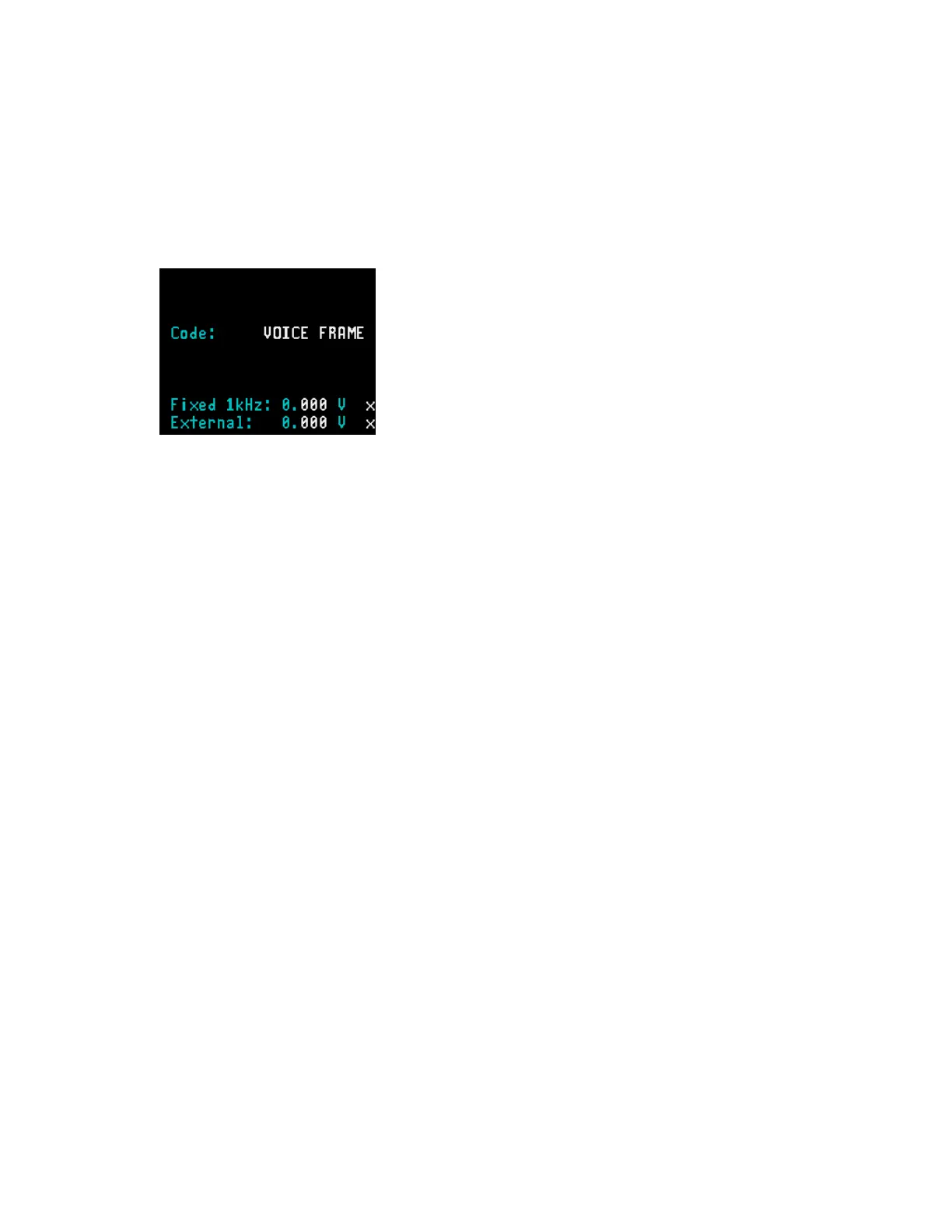
5. Press AUD hardkey and select VOICE
FRAME.
6. Press DISP hardkey to move the cursor to the
Display Zone.
7. Place cursor in the “Display:” field and press
CLEAR SCOPE softkey. The CLEAR
SCOPE screen should appear similar to Figure
22-3. No waveform is present until the
transmitter is turned on.
8. Turn on the Project 25 radio and press PTT.
CAUTION
The analyzer’s built-in RF load dissipates up to 50
W for three minutes and up to 125 W for one
minute. If a high-power transmitter is keyed into
the analyzer for a time long enough to threaten
overheating the power measuring circuitry, the
analyzer’s audible alarm sounds and the display
changes to the RF LOAD OVERTEMPERATURE
warning, signaling the operator to unkey.
9. Move the cursor to “Horiz:” field and select the
desired scale.
10. Move the cursor to “Vert:” field and select the
desired scale.
11. Move the cursor to “Vert Position:” field. Use
move up/move down softkeys or rotary control
to position the recovered audio waveform on a
convenient graticule.
12. Move the cursor to “Horiz Position:” field. Use
move left/move right softkeys or rotary control
to position the recovered audio waveform on a
convenient graticule.
13. Move the cursor to “Mrk:” field.
Press V softkey to display movable
markers that measure voltage differential
(Vp-p).
Press T softkey to display movable
markers that measure time differential (sec).
Press 1/T softkey to display movable
markers that measure reciprocal time
differential (in Hz).
14. Position the markers as desired using TUNING
knob (press toggle marker softkey to select
marker). The movable marker is indicated by a
red line. Observe digital readout of marked
values below “Mrk:” field.
286
 Loading...