10-12
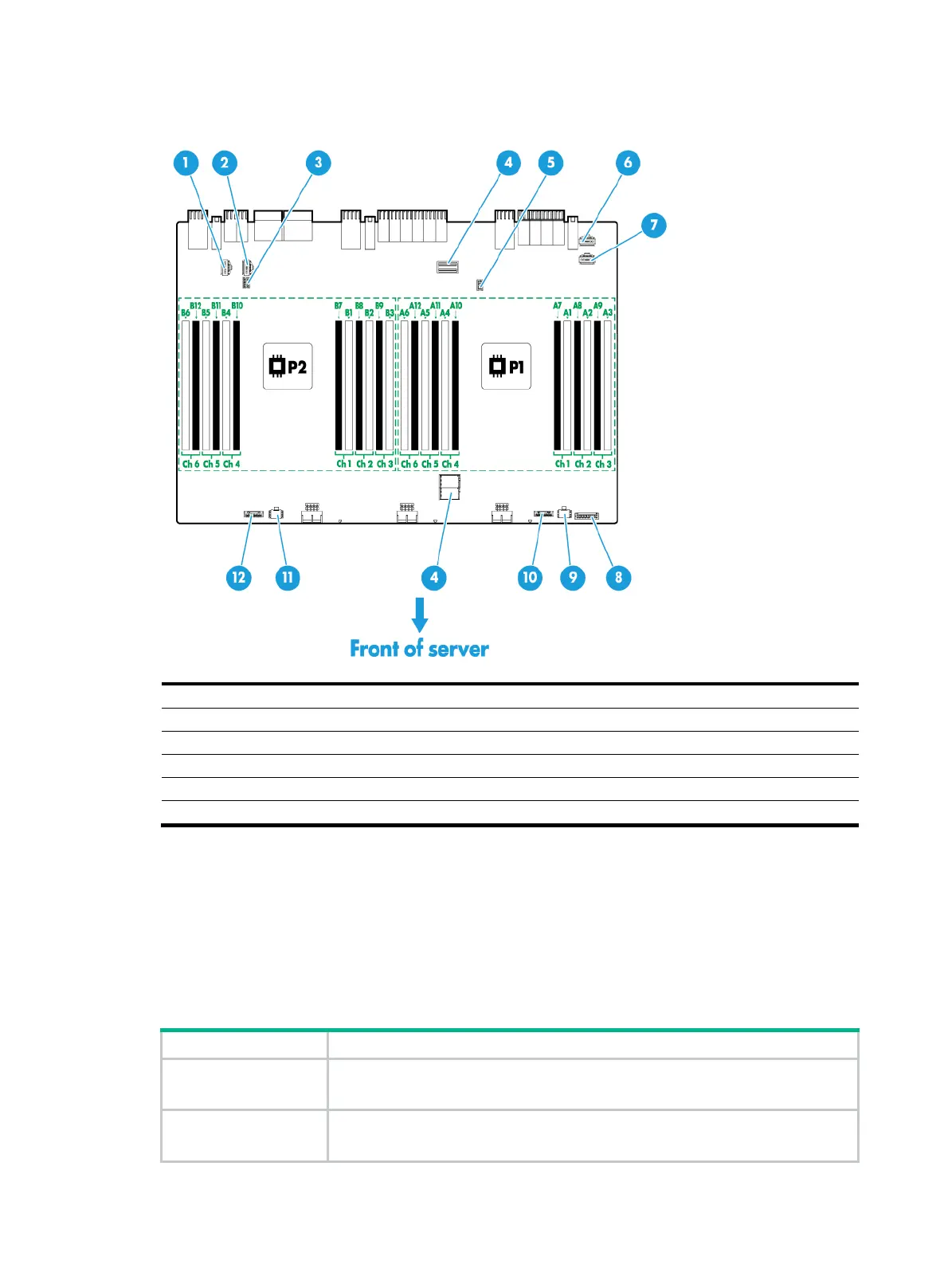
Figure 10-11 Main board components
(1) SAS port B2 (×4 SAS ports) for PCIe riser bay 3 (2) SAS port B1 (×4 SAS ports) for PCIe riser bay 3
(3) Supercapacitor connector 2 for PCIe riser bay 3 (4) PCIe riser connector 0 for processor 2
(5) Supercapacitor connector 1 for PCIe riser bay 1 (6) SAS port A1 (×4 SAS ports) for PCIe riser bay 1
(7) SAS port A2 (×4 SAS ports) for PCIe riser bay 1 (8) LCD connector
(9) Drive backplane power connector 1 (10) Drive backplane AUX connector 1
(11) Drive backplane power connector 2 (12) Drive backplane AUX connector 2
For information about the supported PCIe riser cards and their installation locations, see "Riser
cards."
DIMM slots
The server provides six DIMM channels per processor, 12 channels in total. Each channel contains
one white-coded slot and one black-coded slot, as shown in Table 10-7.
Table 10
-7 DIMM slot numbering and color-coding scheme
Processor DlMM slots
Processor 1
A1 through A6 (white coded)
A7 through A12 (black coded)
Processor 2
B1 through B6 (white coded)
B7 through B12 (black coded)

 Loading...


