7-9
2. Remove the server from the rack, if the space over the server is insufficient. For more
information, see "Removing the server from a rack."
3. Remove the
chassis access panel. The removal process is the same for the compute module
access panel and chassis access panel. For more information, see "Replacing a compute
module a
ccess panel."
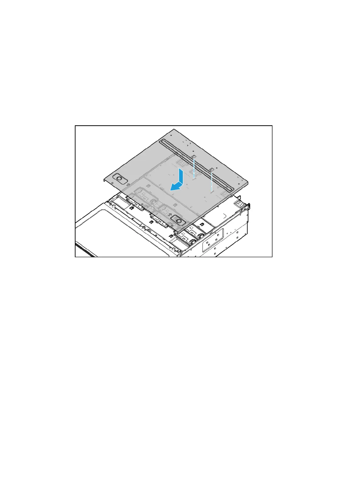
4. Install a new access panel, as shown in Figure 7-11.
a. Place the a
ccess panel on top of the server, with the standouts on the inner side of the
access panel aligned with the square holes at the server rear.
b. Slide the access panel toward the server front until it snaps into place.
Figure 7-11 Installing the chassis access panel
5. Rack-mount the server. For more information, see "Installing the server."
6. Connect the power cord. For more information, see "Connecting the power cord."
7. Powe
r on the server. For more information, see "Powering on the server."
Replacing a power supply
The power supplies are hot swappable.
If more than one operating power supply is present, you can replace a power supply without
powering off the server.
Procedure
1. Power off the server. For more information, see "Powering off the server."
2. Remove the power cord from the power supply, as shown in Figure 7-12:
a. Press the tab
to disengage the ratchet from the tie mount, slide the cable clamp outward,
and then release the tab, as shown by callouts 1 and 2.
b. Open the cable clamp and remove the power cord out of the clamp, as shown by callouts 3
and 4.
c. Unplug the power cord, as shown by callout 5.

 Loading...


