6-13
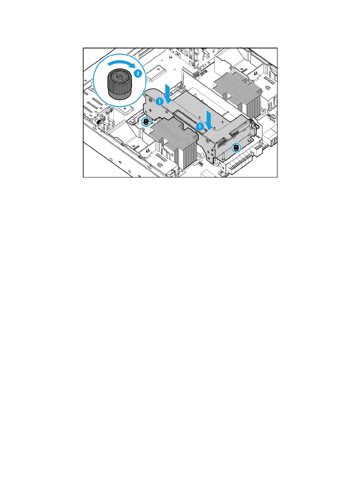
Figure 6-16 Installing the riser card to the compute module
c. Connect PCIe module cables, if any, to the drive backplane.
9. Install the compute module access panel. For more information, see "Replacing a compute
module a
ccess panel."
10. Install the compute module. For more information, see "Installing a compute module."
11. Install the removed security bezel. For more information, see "Installing the security bezel."
12. Connect the power cord. For more information, see "Connecting the power cord."
13. Powe
r on the server. For more information, see "Powering on the server."
Verifying the installation
Log in to HDM to verify that the PCIe module on the riser card is operating correctly. For more
information, see HDM online help.
Installing riser cards and PCIe modules at the server rear
The procedure is the same for installing RS-6*FHHL-G3-1 and RS-6*FHHL-G3-2 riser cards. This
section uses the RS-6*FHHL-G3-1 riser card as an example.
Procedure
1. Power off the server. For more information, see "Powering off the server."
2. Remove the riser card blank. As shown in Figure 6-17, hold the rise
r card blank with your
fingers reaching into the holes on the blank and pull the blank out.

 Loading...


